TLP624-2BVF データシートの表示(PDF) - Toshiba
部品番号
コンポーネント説明
メーカー
TLP624-2BVF Datasheet PDF : 8 Pages
| |||
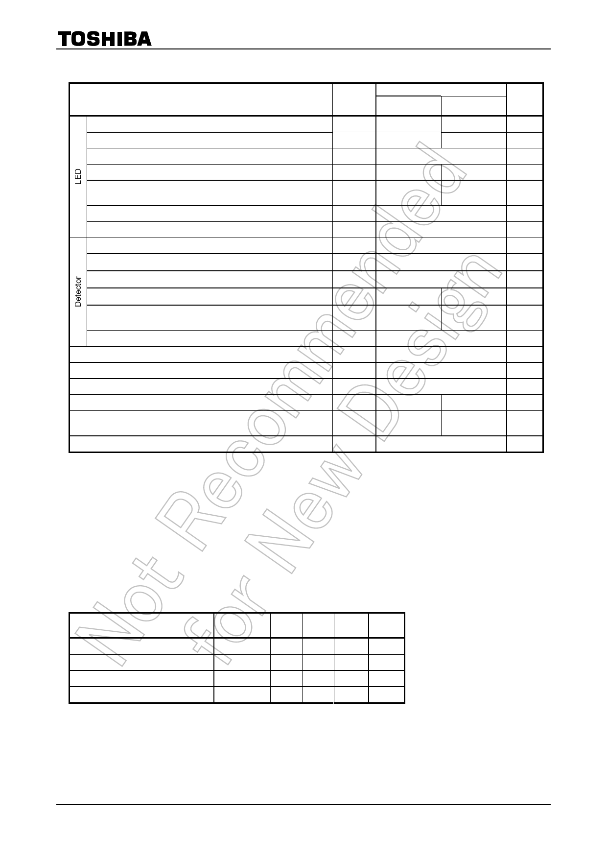
TLP624,TLP624−2,TLP624−4
Absolute Maximum Ratings (Ta = 25°C)
Characteristic
Forward current
Forward current detating
Pulse forward current
Power dissipation(1 Circuit)
Power dissipation derating
(Ta ≥ 25°C, 1 Circuit)
Reverse voltage
Junction temperature
Collector−emitter voltage
Emitter−collector voltage
Collector current
Collector power dissipation(1 circuit)
Collector power dissipation derating
(Ta ≥ 25°C, 1 Circuit)
Junction temperature
Storage temperature range
Operating temperature range
Lead soldering temperature
Total package power dissipation(1 Circuit)
Total package power dissipation derating
(Ta ≥ 25°C, 1 Circuit)
Isolation voltage
Symbol
IF
ΔIF / °C
IFP
PD
Rating
TLP624
TLP624−2
Unit
TLP624−4
60
50
mA
−0.7(Ta ≥ 39°C) −0.5(Ta ≥ 25°C) mA / °C
1(100μs, pulse, 100pps)
A
100
70
mW
ΔPD / °C
−1.0
−0.7
mW / °C
VR
Tj
VCEO
VECO
IC
PC
ΔPC / °C
5
125
55
7
50
150
100
−1.5
−1.0
V
°C
V
V
mA
mW
mW / °C
Tj
Tstg
Popr
Tsol
PT
125
°C
−55~125
°C
−55~100
°C
260(10s)
°C
250
150
mW
ΔPT / °C
−2.5
−1.5
mW / °C
(Note 1) BVS
5000(AC, 1min., RH≤60%)
Vrms
Note: Using continuously under heavy loads (e.g. the application of high temperature/current/voltage and the
significant change in temperature, etc.) may cause this product to decrease in the reliability significantly even
if the operating conditions (i.e. operating temperature/current/voltage, etc.) are within the absolute maximum
ratings.
Please design the appropriate reliability upon reviewing the Toshiba Semiconductor Reliability Handbook
(“Handling Precautions”/“Derating Concept and Methods”) and individual reliability data (i.e. reliability test
report and estimated failure rate, etc).
(Note 1) Device considered a two terminal device: LED side pins shorted together, and detector side pins shorted
together.
Recommended Operating Conditions
Characteristic
Symbol
Min. Typ. Max. Unit
Supply voltage
Forward current
Collector current
Operating temperature
VCC
IF
IC
Topr
―
5
24
V
―
1.6
20
mA
―
1
10
mA
−25 ―
75
°C
Note: Recommended operating conditions are given as a design guideline to obtain expected performance of the
device. Additionally, each item is an independent guideline respectively. In developing designs using this
product, please confirm specified characteristics shown in this document.
2
2007-10-01
Share Link: 