TMP37GRTZ-REEL7(2015) データシートの表示(PDF) - Analog Devices
部品番号
コンポーネント説明
メーカー
TMP37GRTZ-REEL7 Datasheet PDF : 19 Pages
| |||
Data Sheet
APPLICATIONS INFORMATION
SHUTDOWN OPERATION
All TMP35/TMP36/TMP37 devices include a shutdown
capability, which reduces the power supply drain to less than
0.5 µA maximum. This feature, available only in the SOIC_N
and the SOT-23 packages, is TTL/CMOS level-compatible,
provided that the temperature sensor supply voltage is equal in
magnitude to the logic supply voltage. Internal to the TMP35/
TMP36/TMP37 at the SHUTDOWN pin, a pull-up current
source to +VS is connected. This allows the SHUTDOWN pin to
be driven from an open-collector/drain driver. A logic low, or
zero-volt condition, on the SHUTDOWN pin is required to
turn off the output stage. During shutdown, the output of the
temperature sensors becomes high impedance where the
potential of the output pin is then determined by external
circuitry. If the shutdown feature is not used, it is recommended
that the SHUTDOWN pin be connected to +VS (Pin 8 on the
SOIC_N; Pin 2 on the SOT-23).
The shutdown response time of these temperature sensors is
shown in Figure 14, Figure 15, and Figure 16.
MOUNTING CONSIDERATIONS
If the TMP35/TMP36/TMP37 temperature sensors are thermally
attached and protected, they can be used in any temperature
measurement application where the maximum temperature
range of the medium is between −40°C and +125°C. Properly
cemented or glued to the surface of the medium, these sensors
are within 0.01°C of the surface temperature. Caution should be
exercised, especially with T-3 packages, because the leads and
any wiring to the device can act as heat pipes, introducing
errors if the surrounding air-surface interface is not isothermal.
Avoiding this condition is easily achieved by dabbing the leads
of the temper-ature sensor and the hookup wires with a bead of
thermally conductive epoxy. This ensures that the TMP35/TMP36/
TMP37 die temperature is not affected by the surrounding air
temperature. Because plastic IC packaging technology is used,
excessive mechanical stress should be avoided when fastening the
device with a clamp or a screw-on heat tab. Thermally conductive
epoxy or glue, which must be electrically nonconductive, is
recommended under typical mounting conditions.
These temperature sensors, as well as any associated circuitry,
should be kept insulated and dry to avoid leakage and corrosion.
In wet or corrosive environments, any electrically isolated metal
or ceramic well can be used to shield the temperature sensors.
Condensation at very cold temperatures can cause errors and
should be avoided by sealing the device, using electrically non-
conductive epoxy paints or dip or any one of the many printed
circuit board coatings and varnishes.
TMP35/TMP36/TMP37
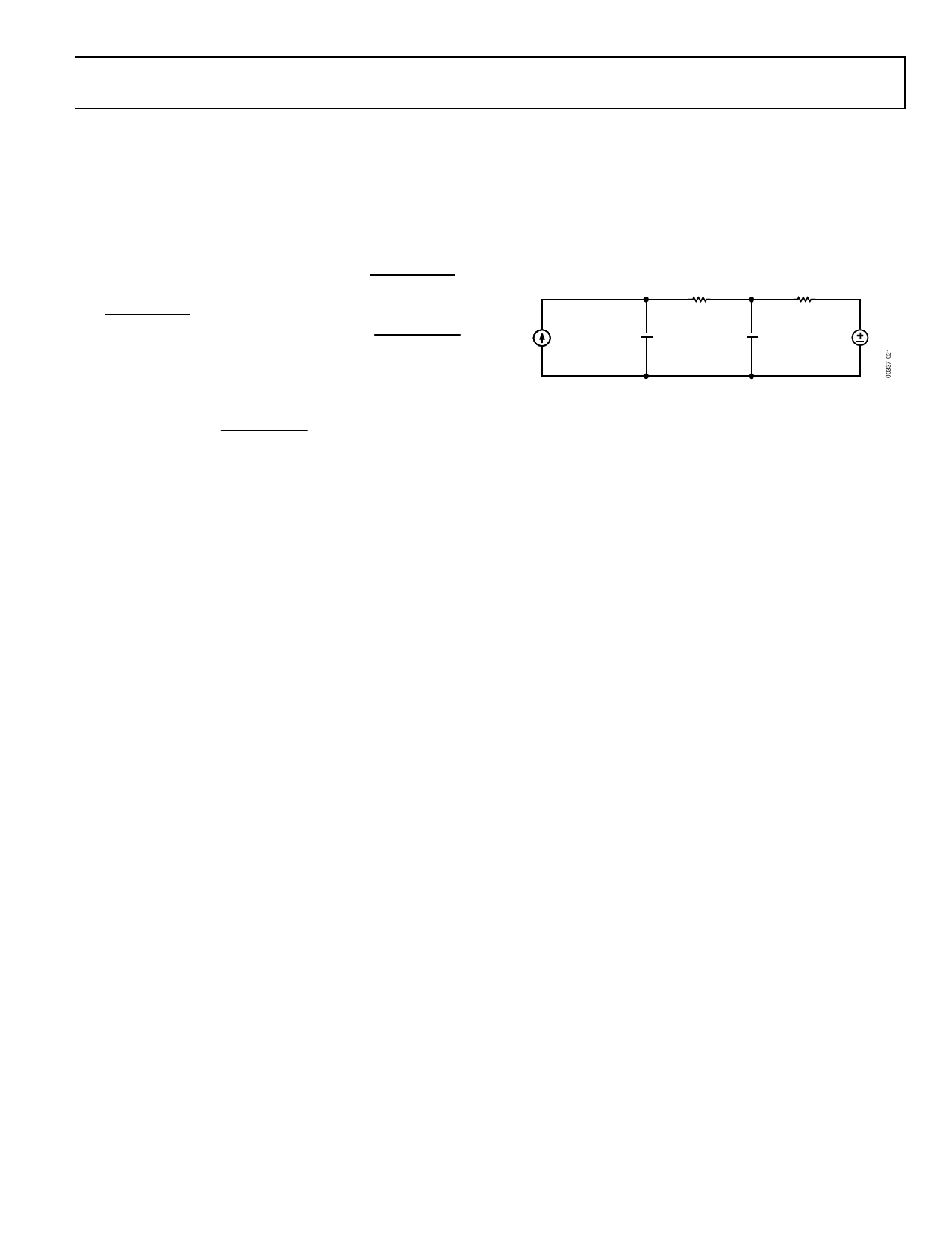
THERMAL ENVIRONMENT EFFECTS
The thermal environment in which the TMP35/TMP36/TMP37
sensors are used determines two important characteristics: self-
heating effects and thermal response time. Figure 23 illustrates a
thermal model of the TMP35/TMP36/TMP37 temperature
sensors, which is useful in under-standing these characteristics.
TJ
θJC
TC
θCA
PD
CCH
CC
TA
Figure 23. Thermal Circuit Model
In the T-3 package, the thermal resistance junction-to-case, θJC,
is 120°C/W. The thermal resistance case-to-ambient, CA, is the
difference between θJA and θJC, and is determined by the char-
acteristics of the thermal connection. The power dissipation of
the temperature sensor, PD, is the product of the total voltage
across the device and its total supply current, including any
current delivered to the load. The rise in die temperature above
the ambient temperature of the medium is given by
TJ = PD × (θJC + θCA) + TA
Thus, the die temperature rise of a TMP35 SOT-23 package
mounted into a socket in still air at 25°C and driven from a 5 V
supply is less than 0.04°C.
The transient response of the TMP35/TMP36/TMP37 sensors
to a step change in the temperature is determined by the
thermal resistances and the thermal capacities of the die, CCH,
and the case, CC. The thermal capacity of CC varies with the
measurement medium because it includes anything in direct
contact with the package. In all practical cases, the thermal
capacity of CC is the limiting factor in the thermal response time
of the sensor and can be represented by a single-pole RC time
constant response. Figure 17 and Figure 19 show the thermal
response time of the TMP35/TMP36/TMP37 sensors under
various conditions. The thermal time constant of a temperature
sensor is defined as the time required for the sensor to reach
63.2% of the final value for a step change in the temperature.
For example, the thermal time constant of a TMP35 SOIC
package sensor mounted onto a 0.5" × 0.3" PCB is less than
50 sec in air, whereas in a stirred oil bath, the time constant is
less than 3 sec.
Rev. H | Page 9 of 19
Share Link: 