TPS830 データシートの表示(PDF) - Toshiba
部品番号
コンポーネント説明
メーカー
TPS830 Datasheet PDF : 6 Pages
| |||
TPS830(F)
Optical And Electrical Characteristics (VCC = 5V, Ta = 25°C, C = 1000pF: Note 1)
Characteristic
Symbol
Test Condition
Min
Typ.
Max
Unit
Supply voltage
Supply current
Electromagnetic sensitivity
Transmission range
High−level output voltage
Low−level output voltage
On pulse width
Off pulse width
Carrier frequency
Peak sensitivity wavelength
Radiation angle
VCC
―
3
5
7
V
ICC
E=0
―
1.2
3
mA
ES
(Note 5) ―
250
―
Vp−p / m
L (Note 3) The burst wave shown in Note
3
6
―
m
VOH
4 is transmitted by a standard
4
―
―
V
VOL
TON
TOFF
transmitter (Note 2).
External light intensity < 500 lx
Output current < 10μA
―
―
0.5
V
16
25
40
μs
―
63
―
μs
fo
―
―
455
―
kHz
λP
―
―
900
―
nm
θH
Horizontal angle, L / 2 (Note 6) ±55
±63
―
°
θV
Vertical angle, L / 2
(Note 6) ±25
±30
―
°
Note 1: Measurements for the TPS830(F) are based on a standard circuit which includes a 1000−pF capacitor
between VO and GND to prevent oscillation.
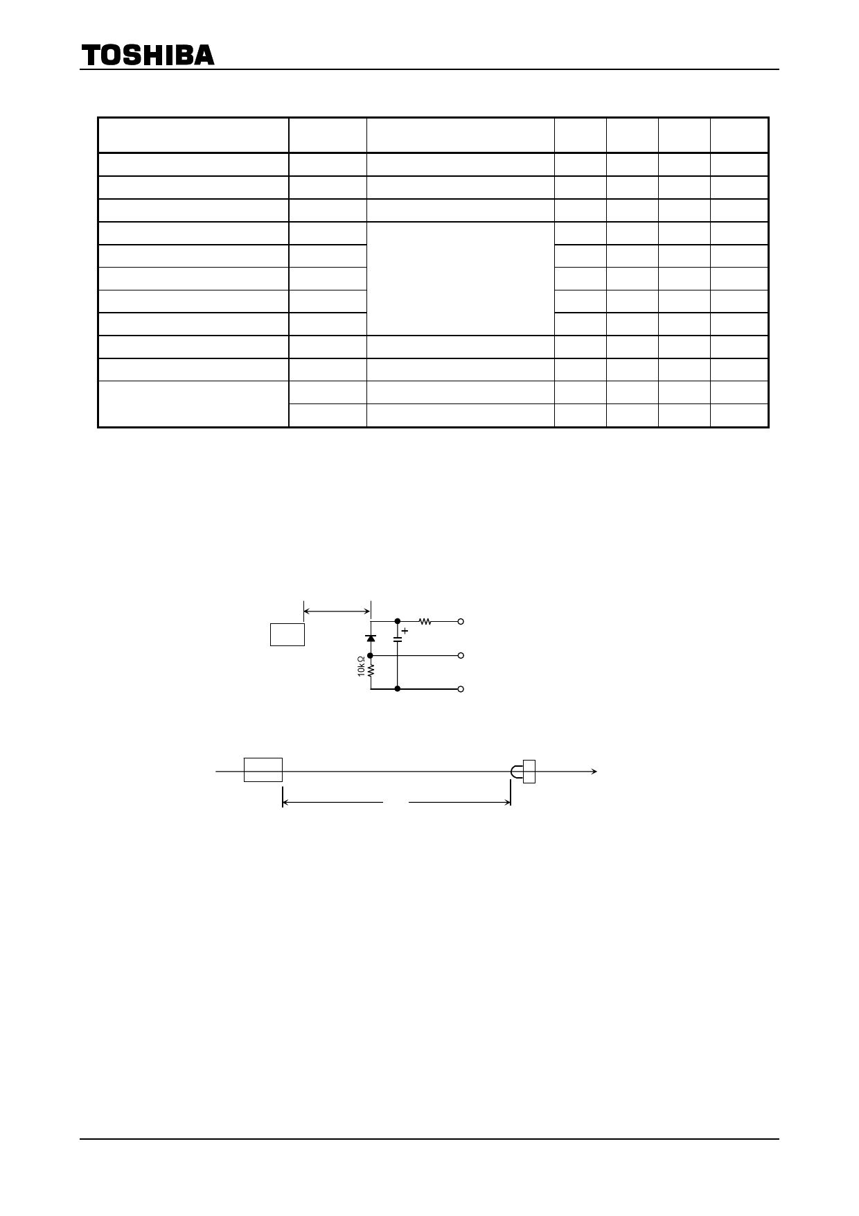
Note 2: Standard transmitter
In the figure above, the transmitter output VOUT is 80m Vpp.
The TPS703(F) in this application has a short−circuit current of Isc = 1.24μA when measured at E =
0.1mW/cm2. (E is the radiant incidence when a CIE standard light source A is used.)
20cm
TPS703(F)
Transmitter
(TLN115A(F) is used.)
f0 = 455kHz
Duty = 50%
10kΩ
10μF
+10V
VOUT
GND
Note 3: Transmission range L
Standard transmitter (TLN105B(F))
L
L is the maximum distance at which burst waves can be received from the transmitter unit, and at which
data can be processed by the receiver unit.
Note that when signals other than the recommended burst wave are transmitted, the transmission range
may be reduced or a malfunction may occur.
(*) The TLN105B(F) is used as the standard LED transmitter.
If the TLN231(F) is used instead, the transmission range is 1.2 times that of the TLN105B(F).
Example: 6m (with TLN105B(F)) ⇒ 10.1m (with TLN231(F))
2
2007-10-01
Share Link: 