CH224ATF(1999) データシートの表示(PDF) - Cermetek Microelectronics
部品番号
コンポーネント説明
メーカー
CH224ATF Datasheet PDF : 14 Pages
| |||
PRELIMINARY
CH224ATF
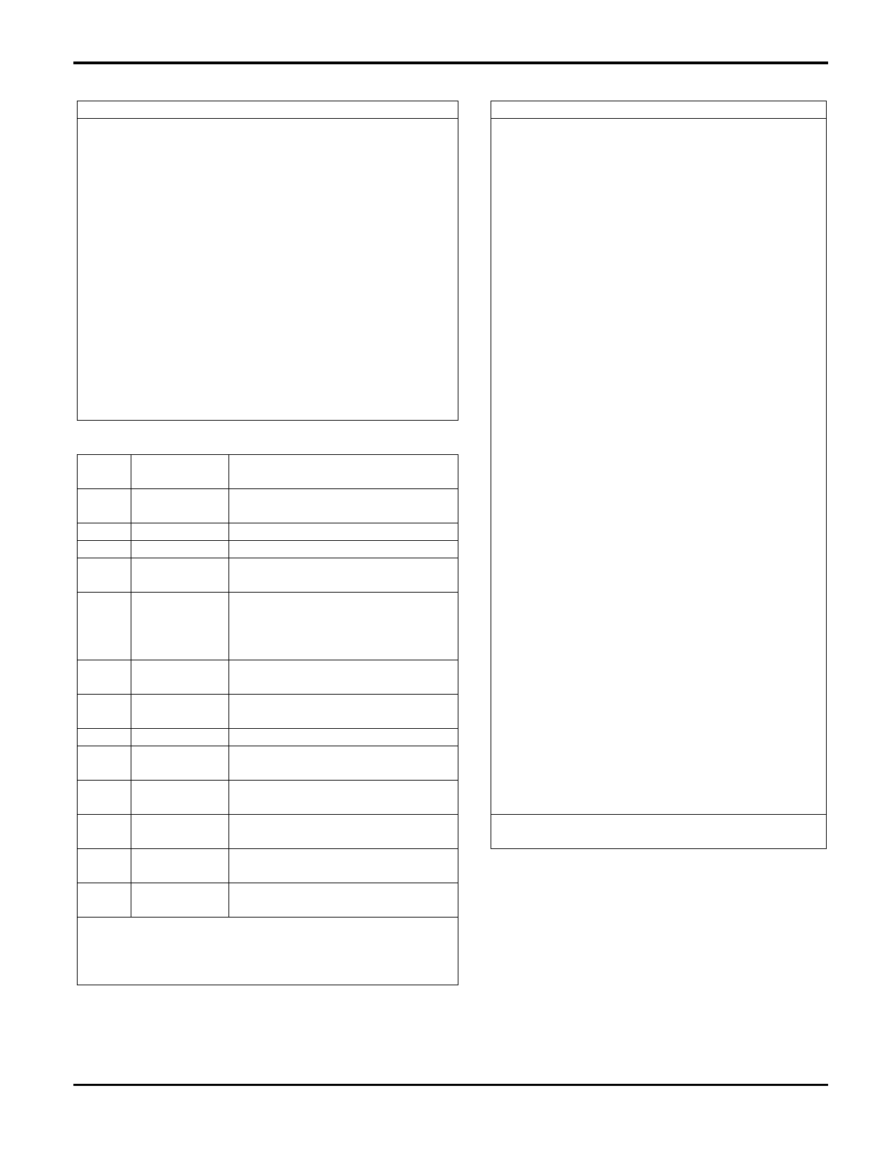
Table 5. Results Codes & Messages
Digit Word Code
Meaning
Code
0
OK
1
CONNECT
Command line executed without
errors
Connection at 300bps
2
RING
Ringing signal detected
3
NO CARRIER Carrier lost or never present
4
ERROR
Invalid command, checksum, error
in command line, or command line
exceeds 40 characters
5
CONNECT 1200 Connection at 1200 bps
6
NO DIAL TONE No dialtone detected
7
BUSY
Busy signal detected
8
NO ANSWER No silence detected when dialing a
system not providing a dialtone
10
CONNECT 2400 Connection at 2400 bps
+F4
+FCERROR
Fax carrier error
13
DATA
Connected as data modem during
auto answer
15
FAX
Connected as fax modem during
auto answer
Data/Fax Auto Answering
The modem can automatically determine if the incoming
call is from a data or fax modem, make the appropriate
connection, and inform the DTE of the connection type.
AT Command Format
Each command line must start with the AT prefix and be
terminated with a carriage return (CR). Several commands
may be included on one command line. A command line
may contain up to 40 characters excluding the AT prefix and
the terminating CR. A separator is not required between
data commands. A semicolon (;) separator is required
between fax commands.
AT commands are composed of 10-bit ASCII encoded
asynchronous characters. The character format in data mode
is 8 data bits with no parity, or 7 data bits with even, odd, or
no (two stop bits) parity, at a data rate of 19200, 2400, 1200,
or 300 bps. The character format in fax mode is 8 data bits
with no parity at 19200 bps.
Data Modulation
The data modulation conforms to V.29, V.27 ter, V.22 bis,
V.22, V.21, Bell212A, or Bell 103, depending on the
selected configuration. Transmitter and receiver spectrum
shaping is provided in accordance with the applicable
standard.
Equalization
Automatic adaptive qualization as well as fixed
compromised equalization is provided to
compensate for line distortions and to minimize
the effects of the intersymbol interference.
Scrambler/Descrambler
The modem incorporates a self-synchronizing
scrambler/ descrambler satisfying the applicable
CCITT or Bell requirements.
Transmit Level
The transmit level is –10 dBm +1 dB (at TIP and
RING).
Answer Tone: An answer tone of 2100 Hz
(V.22bis, V.22, or T.30) or 2225 Hz (Bell 212A or
103) is generated.
Guard Tone: An 1800 Hz guard tone can be
generated in all data modes.
Calling Tone: A 1100 Hz (0.5 seconds on, 3
seconds on, 3 seconds off) calling tone (T.30) is
generated in the originate fax mode.
Receive Level
The receiver satisfies performance rquirements for
a received signal from –9 dBm to –43 dBm. The
carrier detect is ON at –43 dBm and OFF at –48
dBm with a minimum of 2 dB hysteresis.
Receiver Tracking
The modem can accommodate carrier frequency
offset up to +7 Hz, and a transmit timing error of
+ 0.01% (V.22 bis or V.27 ter) or + 0.02% (V.22
or Bell 212A).
Low Power Sleep Mode
To conserve power, the CH224ATF is configured
for idle (power down) mode. Idle mode is entered
whenever the modem is inactive beyond the time
value specified by S24.
The idle mode allows reduced power consumption
with automatic recovery without additional
circuitry. The modem exits Idle mode and returns
to full operation whenever a ring signal occurs, the
DTE writes to the modem (parallel interface), or
~DTR or ~TXD is asserted (serial interface).
©1999 Cermetek Microelectronics, Inc.
4
Document No. 607-0005 Rev.A (11/99)
Share Link: 