UEI-3.3 データシートの表示(PDF) - Murata Power Solutions
部品番号
コンポーネント説明
メーカー
UEI-3.3 Datasheet PDF : 12 Pages
| |||
UEI Series
50-60W Isolated Wide-Range DC/DC Converters
OVP circuit may inadvertantly shut down the converter. If the maximum power
is exceeded, the converter may enter current limiting. If the power is exceeded
for an extended period, the converter may overheat and encounter overtem-
perature shut down.
CAUTION: Be careful of external electrical noise. The Trim input is a senstive
input to the converter’s feedback control loop. Excessive electrical noise may
cause instability or oscillation. Keep external connections short to the Trim
input. Use shielding if needed.
2
−INPUT
6
+OUTPUT
5
+SENSE
4 ON/OFF
CONTROL
TRIM
−SENSE
9
R TRIM UP
8
LOAD
1 +INPUT
7
−OUTPUT
Figure 7 – Trim adjustments to increase Output Voltage using a Fixed Resistor
Trim Equations
Trim Up
<Connect trim resistor
between Trim and –Sense>
Trim Down
<Connect trim resistor
between Trim and +Sense>
UEI-3.3/15-Q12, -3.3/18-Q48
12775
RT UP (:) =
– 2050
VO – 3.3
5110 (Vo - 2.5)
RTDOWN (:) =
– 2050
3.3 – VO
UEI-5/10-Q12, -5/12-Q48
RT UP (:) =
12775
– 2050
VO – 5
5110 (Vo - 2.5)
RTDOWN (:) =
– 2050
5 – VO
UEI-12/4.2-Q12, -12/5-Q48
RT UP (:) =
25000
– 5110
VO – 12
10000 (Vo-2.5)
RTDOWN (:) =
–5110
12 – VO
UEI-15/3.3-Q12, -Q48
RT UP (:) =
25000
– 5110
VO – 15
10000 (Vo-2.5)
RTDOWN (:) =
–5110
15 – VO
Positive: Standard models are enabled when the On/Off pin is left open or
is pulled high to +15V with respect to –VIN. An internal bias current causes the
open pin to rise to +15V. Some models will also turn on at lower intermediate
voltages (see Specifications). Positive-polarity devices are disabled when the
On/Off is grounded or brought to within a low voltage (see Specifications) with
respect to –VIN.
Negative: Optional negative-polarity devices are on (enabled) when the On/
Off is grounded or brought to within a low voltage (see Specifications) with
respect to –VIN. The device is off (disabled) when the On/Off is left open or is
pulled high to +15VDC Max. with respect to –VIN.
Dynamic control of the On/Off function should be able to sink appropriate
signal current when brought low and withstand appropriate voltage when
brought high. Be aware too that there is a finite time in milliseconds (see
Specifications) between the time of On/Off Control activation and stable,
regulated output. This time will vary slightly with output load type and current
and input conditions.
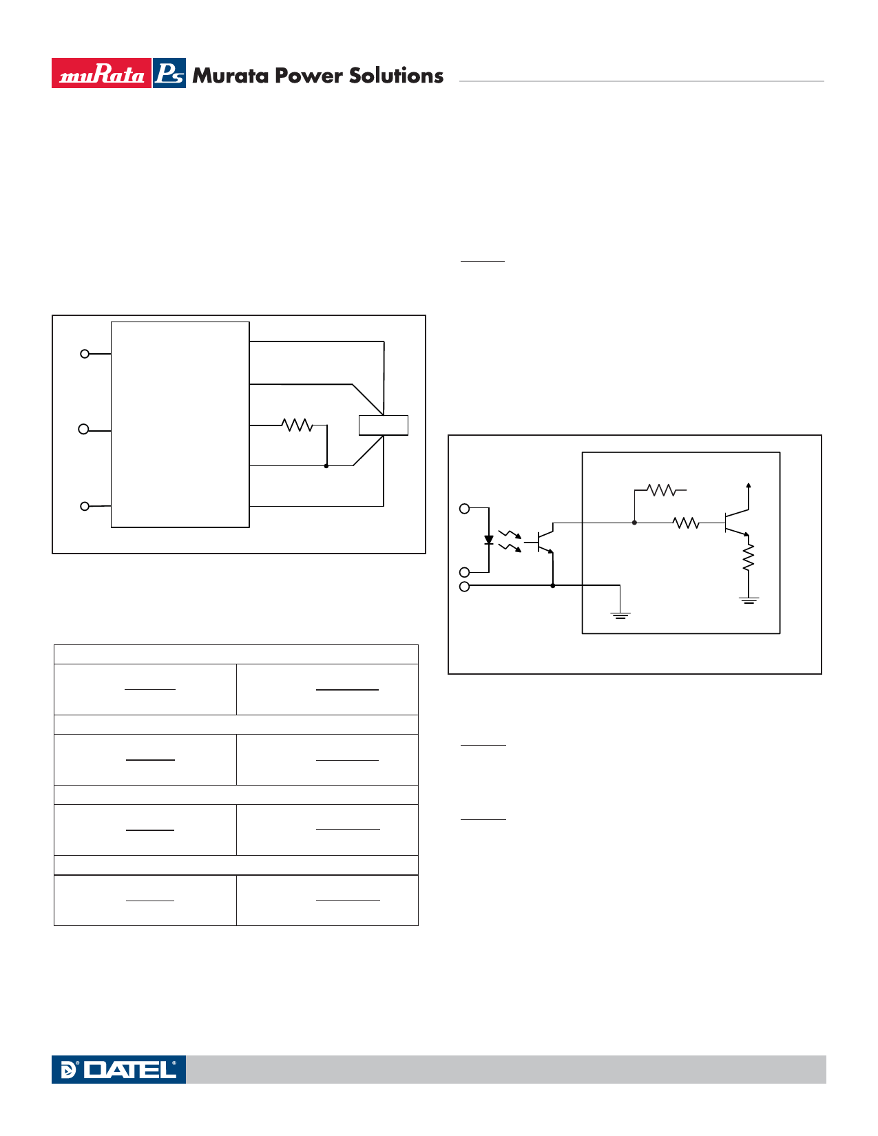
3
ON/OFF
CONTROL
1 -INPUT
+ Vcc
Figure 8 – Driving the On/Off Control Pin (suggested circuit)
There are two CAUTIONs for the On/Off Control:
CAUTION: While it is possible to control the On/Off with external logic if you
carefully observe the voltage levels, the preferred circuit is either an open
drain/open collector transistor or a relay (which can thereupon be controlled by
logic).
CAUTION: Do not apply voltages to the On/Off pin when there is no input
power voltage. Otherwise the converter may be permanently damaged.
Where Vo = Desired output voltage. Adjustment accuracy is subject to resis-
tor tolerances and factory-adjusted output accuracy. Mount trim resistor close
to converter. Use short leads.
Remote On/Off Control
On the input side, a remote On/Off Control can be ordered with either polarity.
www.murata-ps.com
Technical enquiries email: sales@murata-ps.com, tel: +1 508 339 3000
MDC_UEI Series 50-60W.B24 Page 9 of 12
Share Link: 