MPSA77 データシートの表示(PDF) - Motorola => Freescale
部品番号
コンポーネント説明
メーカー
MPSA77 Datasheet PDF : 4 Pages
| |||
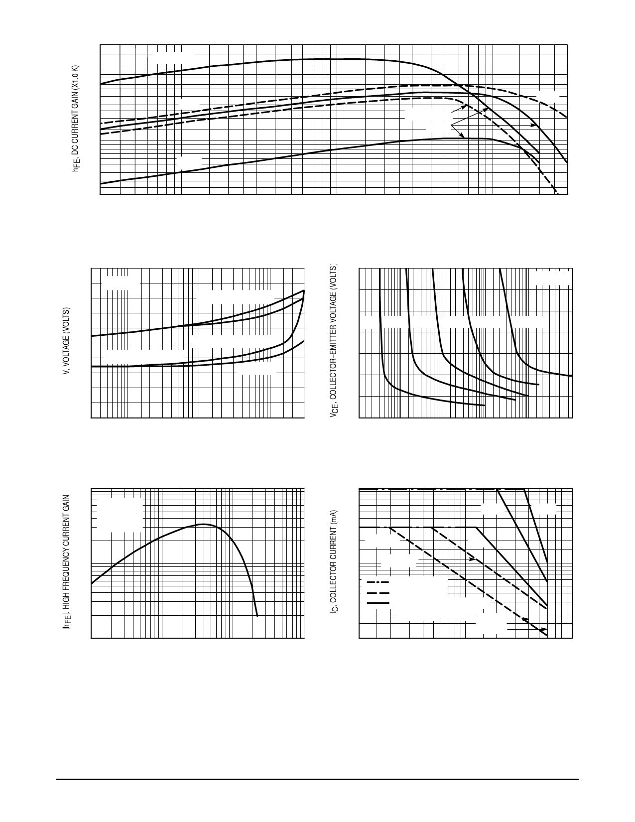
MPSA75 MPSA77
200
TA = 125°C
100
70
50
30
25°C
20
10
7.0
5.0
3.0
2.0
–0.3
–55°C
–0.5 –0.7 –1.0
VCE = –2.0 V
–5.0 V
–2.0 –3.0
–5.0 –7.0 –10
–20 –30
IC, COLLECTOR CURRENT (mA)
Figure 1. DC Current Gain
–50 –70 –100
–10 V
–200 –300
–2.0
TA = 25°C
–1.6
VBE(sat) @ IC/IB = 100
–1.2
VBE(on) @ VCE = –5.0 V
–0.8 VCE(sat) @ IC/IB = 1000
IC/IB = 100
–0.4
0
–0.3 –0.5 –1.0
–2 –3 –5 –10 –20 –30 –50 –100 –200 –300
IC, COLLECTOR CURRENT (mA)
Figure 2. “On” Voltage
–2.0
TA = 25°C
–1.8
–1.6
IC = –10 mA –50 mA –100 mA –175 mA
–1.4
–300 mA
–1.2
–1.0
–0.8
–0.6
–0.1–0.2 –0.5 –1 –2 –5 –10 –20 –50 –100–200–500 –1K–2K –5K–10K
IB, BASE CURRENT (µA)
Figure 3. Collector Saturation Region
10
VCE = –5.0 V
4.0 f = 100 MHz
3.0 TA = 25°C
2.0
1.0
0.4
0.2
0.1
–1.0 –2.0
–5.0 –10 –20 –50 –100 –200
IC, COLLECTOR CURRENT (mA)
–500 –1K
Figure 4. High Frequency Current Gain
–1000
–300
–200 TA = 25°C
–100
TC = 25°C
1.0 ms
1.0 s
100 µs
–50
–20
–10
–1.0
CURRENT LIMIT
THERMAL LIMIT
SECOND BREAKDOWN LIMIT
(DUTY CYCLE ≤ 10%) MPSA75
MPSA77
–2.0 –4.0 –6.0 –10 –20 –40 –60
VCE, COLLECTOR VOLTAGE (VOLTS)
Figure 5. Active Region, Safe Operating Area
2
Motorola Small–Signal Transistors, FETs and Diodes Device Data
Share Link: 