VCC6-V データシートの表示(PDF) - Vectron International
部品番号
コンポーネント説明
メーカー
VCC6-V Datasheet PDF : 6 Pages
| |||
VCC6-L/V Series, 2.5 and 3.3V LVDS Crystal Oscillator
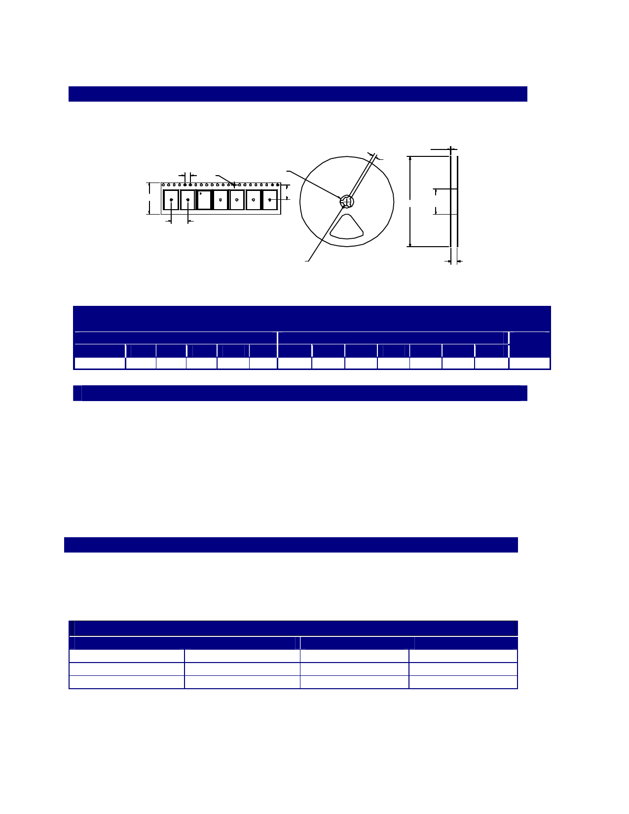
Tape and Reel
D
C
A
E
G
B
H
J
F
L
I
K
Table 4. Tape and Reel Dimensions (mm)
Tape Dimensions
Reel Dimensions
# Per
Product A
B
C
DE
F
G
H
I
J
K
L
Reel
VCC6
16
7. 5
1.5
4
8
2
21
13
60
2
17
180
250
Enable/Disable Functional Description
Under normal operation the Enable/Disable is left open, or set to a logic high state, the VCC6 is an
oscillation mode and outputs are active. When the E/D is set to a logic low, the oscillator stops and the
both the output and complementary outputs are in a high impedance state. This helps facilitate board
testing and troubleshooting.
Power Saving Pull-Up Resistor
The E/D pull-up resistor changes in response to the input logic level; the pull-up resistor is a large value
when E/D is set to a logic low, which reduces the current consumed. When E/D is open, or set to a logic
high, the pull-up resistance becomes a smaller value which helps decrease the effects of external noise.
Absolute Maximum Ratings
Stresses in excess of the absolute maximum ratings can permanently damage the device. Functional
operation is not implied at these or any other conditions in excess of conditions represented in the
operational sections of this data sheet. Exposure to absolute maximum ratings for extended periods may
adversely affect device reliability.
Table 5. Absolute Maximum Ratings
Parameter
Symbol
Power Supply
Enable/Disable
Storage Temperature
VDD
VIN
Tstorage
Ratings
-0.5 to +7.0
-0.5 to VDD+0.5
-55/125
Unit
Vdc
Vdc
°C
Vectron International 267 Lowell Rd, Hudson NH 03051 Tel: 1-88-VECTRON-1 e-mail: vectron@vectron.com
Share Link: 