VI-HAM-CM データシートの表示(PDF) - Vicor
部品番号
コンポーネント説明
メーカー
VI-HAM-CM Datasheet PDF : 6 Pages
| |||
12 1-800-735-6200
VI-HAM Protection Features
(continued)
Inrush Current Limit
The VI-HAM contains inrush current
protection in the form of a PTC and a
shunt device. The same PTC is used for
overcurrent protection on the output.
Input Transient Overvoltage Surge Protection
This function is included in all VI-HAM
compatible filters. If any other filter is used
this function must be provided externally,
typically by a transient suppressor.
• Safety Note •
All VI-HAM configurations must be
preceded by an appropriately rated fast-blow
3AG fuse ahead of the line filter. This fuse
would be a 10A for a single VI-HAM
connected to line. For fusing information on
other VI-HAM configurations, please
contact Vicor’s Application Engineering
Department.
Compatible Modules
Over the full range of input voltages (85 to 264 Vac),
the output varies from 260 to 415Vdc. Therefore
the modules used with the VI-HAM are from the
VI-260 and VI-J60 families.
When ordering add the prefix VI- to the part
number below; i.e., VI-260-CU.
VI-200 Family
5V 12V 15V 24V 48V Output
260-CU 261-CU 262-CU 263-CU 264-CU 200W
260-CV 261-CV 262-CV 263-CV 264-CV 150W
260-CW 261-CW 262-CW 263-CW 264-CW 100W
260-CX 261-CX 262-CX 263-CX 264-CX 75W
260-CY 261-CY 262-CY 263-CY 264-CY 50W
Framed area available as boosters.
Change VI-2XX-XX to VI-BXX-XX.
VI-J00 Family
5V 12V 15V 24V 48V Output
J60-CW J61-CW J62-CW J63-CW J64-CW 100W
J60-CX J61-CX J62-CX J63-CX J64-CX 75W
J60-CY J61-CY J62-CY J63-CY J64-CY 50W
J60-CZ J61-CZ J62-CZ J63-CZ J64-CZ 25W
Filter Requirements for the VI-HAM
The VI-HAM requires an external filter to meet international standards for conducted
EMI/RFI emissions. P/N 07818 (for use up to 600W) incorporates transient protection for
compliance with IEC 61000-4-5 Level 3 and meets conducted emissions standards
EN55022 and FCC Part 15 Level A (minimum loading of 150W required).
VI-HAM Configurations
VI-HAM-CM Driver HAM: Fully configured power factor correcting front end.
VI-HAMD-CM Driver HAM: No internal bridge rectifier or synchronization diodes.
VI-BAMD-CM Booster HAM: Companion module to VI-HAMD-CM used for
additional output power. No internal bridge rectifier.
Use the VI-HAM-CM for applications requiring up to 600W from the front end.
For applications in excess of 600W, it is not possible to simply parallel two driver
VI-HAMs due to conflicting control loops. Gate Out to Gate In connections on
respective driver/boosters are used to ensure that the power train of the VI-HAMs
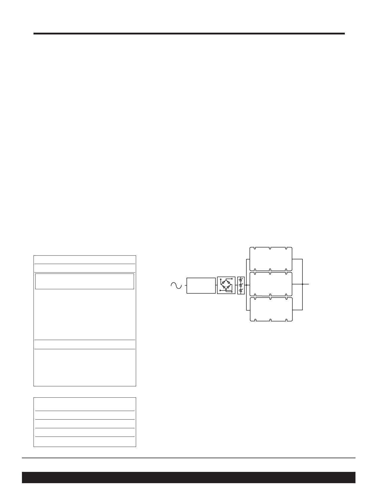
current-share. However, this does not ensure that the diodes in the lower half of the
bridge rectifier will current-share. A solution for this situation is illustrated (see Fig. 8).
Vac
Line Filter
VI-HAMD
VI-BAMD
VI-BAMD
Figure 8 • VI-HAMD with Booster HAMs (BAMDs) — No Internal Bridge Rectifier
A solution to bridge rectifier current sharing issues is to remove the bridge rectifier
from each VI-HAM and use one diode bridge sized to handle the entire load.
Approximately 25% of the heat is removed from the VI-HAM in this approach; use a
VI-HAMD-CM with one or more VI-BAMD-CMs. Note: Synchronization diodes are
required when using this approach (see Fig. 10).
Prod. Baseplate
Grade Temp.
Storage
Temp.
Model
E -10°C to +85°C -20°C to +100°C VI-HAM-EM
C -25°C to +85°C -40°C to +100°C VI-HAM-CM
I -40°C to +85°C -55°C to +100°C VI-HAM-IM
M -55°C to +85°C -65°C to +100°C VI-HAM-MM
Vicor Corp. Tel: 800-735-6200, 978-470-2900 Fax: 978-475-6715
HAM, Harmonic Attenuator Module
Set your site on VICOR at www.vicorpower.com
Rev. 1.1
Page 3 of 6
Share Link: 