VIPER12A データシートの表示(PDF) - STMicroelectronics
部品番号
コンポーネント説明
メーカー
VIPER12A Datasheet PDF : 15 Pages
| |||
VIPer12ADIP / VIPer12AS
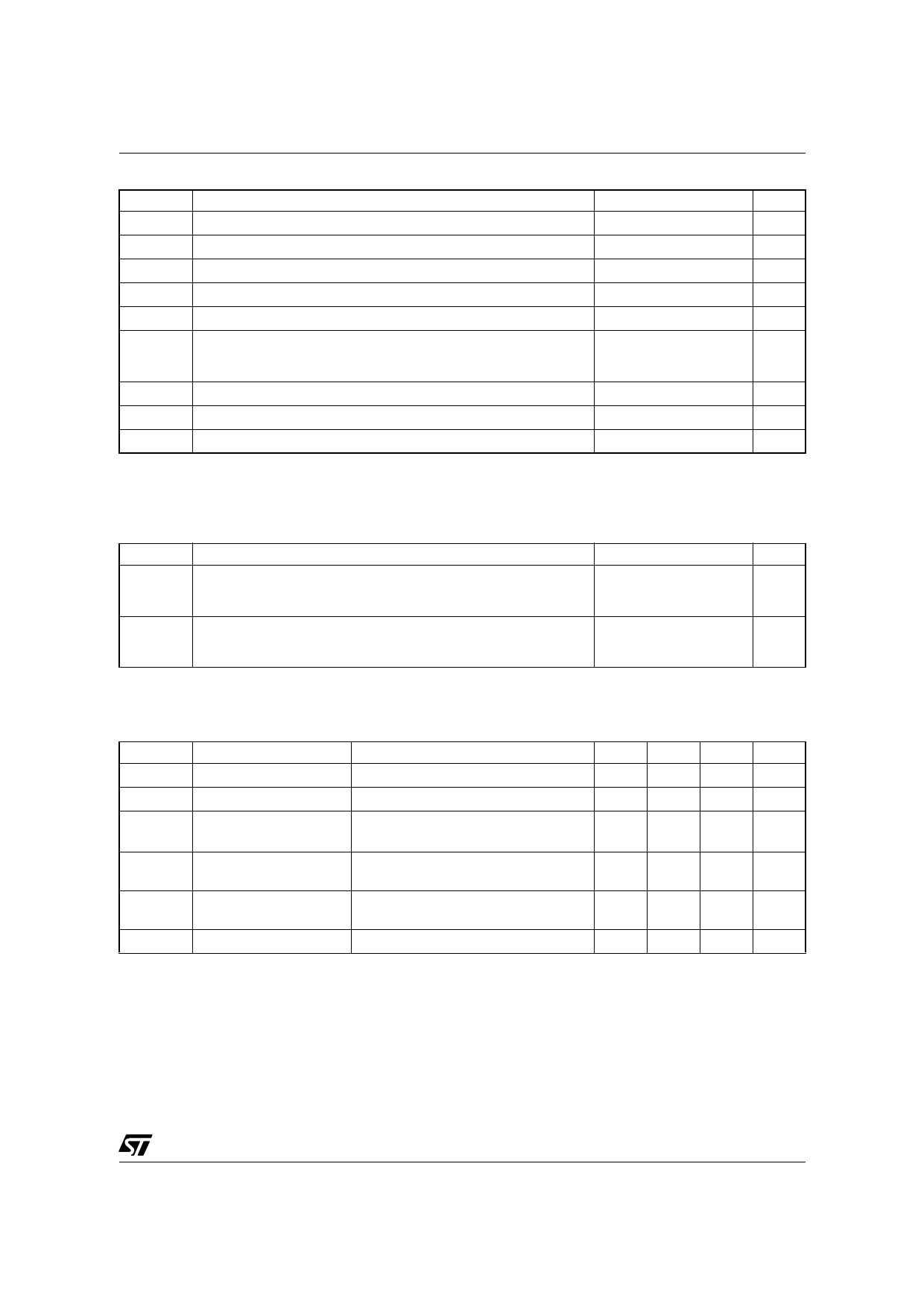
ABSOLUTE MAXIMUM RATINGS
Symbol
Parameter
Value
Unit
VDS(sw) Switching Drain Source Voltage (Tj=25 ... 125°C)
(See note 1)
-0.3 ... 730
V
VDS(st) Start Up Drain Source Voltage (Tj=25 ... 125°C)
(See note 2)
-0.3 ... 400
V
ID
Continuous Drain Current
Internally limited
A
VDD Supply Voltage
0 ... 50
V
IFB
Feedback Current
3
mA
VESD
Electrostatic Discharge:
Machine Model (R=0Ω; C=200pF)
Charged Device Model
200
V
1.5
kV
Tj
Junction Operating Temperature
Internally limited
°C
Tc
Case Operating Temperature
-40 to 150
°C
Tstg
Storage Temperature
-55 to 150
°C
Note: 1. This parameter applies when the start up current source is off. This is the case when the VDD voltage has reached VDDon and
remains above VDDoff.
2. This parameter applies when the start up current source is on. This is the case when the VDD voltage has not yet reached VDDon
or has fallen below VDDoff.
THERMAL DATA
Symbol
Parameter
Max Value
Unit
Thermal Resistance Junction-Pins for:
Rthj-case SO-8
DIP8
25
°C/W
15
Thermal Resistance Junction-Ambient for:
Rthj-amb SO-8
(See note 1)
55
DIP8
(See note 1)
45
°C/W
Note: 1. When mounted on a standard single-sided FR4 board with 200 mm² of Cu (at least 35 µm thick) connected to all DRAIN pins.
ELECTRICAL CHARACTERISTICS (Tj=25°C, VDD=18V, unless otherwise specified)
POWER SECTION
Symbol
Parameter
Test Conditions
Min. Typ. Max. Unit
BVDSS Drain-Source Voltage
ID=1mA; VFB=2V
730
V
IDSS Off State Drain Current VDS=500V; VFB=2V; Tj=125°C
0.1
mA
RDSon
Static Drain-Source
On State Resistance
ID=0.2A
ID=0.2A; Tj=100°C
27
30
54
Ω
tf
Fall Time
ID=0.1A; VIN=300V
(See fig.1)
100
ns
(See note 1)
tr
Rise Time
ID=0.2A; VIN=300V
(See fig.1)
(See note 1)
50
ns
Coss Drain Capacitance
VDS=25V
40
pF
Note: 1. On clamped inductive load
3/15
Share Link: 