VIPER12A データシートの表示(PDF) - STMicroelectronics
部品番号
コンポーネント説明
メーカー
VIPER12A Datasheet PDF : 15 Pages
| |||
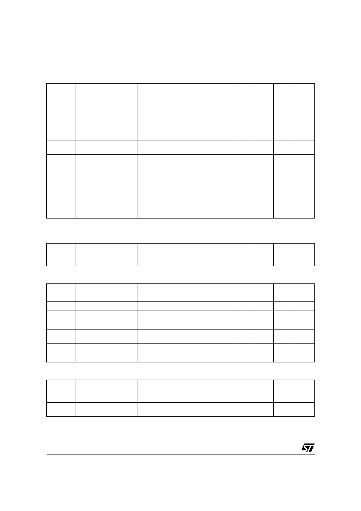
VIPer12ADIP / VIPer12AS
ELECTRICAL CHARACTERISTICS (Tj=25°C, VDD=18V, unless otherwise specified)
SUPPLY SECTION
Symbol
Parameter
Test Conditions
Min. Typ. Max. Unit
IDDch
Start Up Charging
Current
VDS=100V; VDD=5V ...VDDon (See fig. 2)
-1
mA
IDDoff
Start Up Charging
Current
in Thermal Shutdown
VDD=5V; VDS=100V
Tj > TSD - THYST
0
mA
IDD0
Operating Supply Current
Not Switching
IFB=2mA
3
5
mA
IDD1
Operating Supply Current
Switching
IFB=0.5mA; ID=50mA
(Note 1)
4.5
mA
DRST
VDDoff
Restart Duty Cycle
VDD Undervoltage
Shutdown Threshold
(See fig. 3)
16
%
(See fig. 2 & 3) 7
8
9
V
VDDon
VDDhyst
VDD Start Up Threshold
VDD Threshold
Hysteresis
(See fig. 2 & 3) 13 14.5 16
V
(See fig. 2) 5.8
6.5
7.2
V
VDDovp
VDD Overvoltage
Threshold
38
42
46
V
Note: 1. These test conditions obtained with a resistive load are leading to the maximum conduction time of the device.
OSCILLATOR SECTION
Symbol
Parameter
FOSC
Oscillator Frequency
Total Variation
Test Conditions
VDD=VDDoff ... 35V; Tj=0 ... 100°C
Min. Typ. Max. Unit
54
60
66
kHz
PWM COMPARATOR SECTION
Symbol
Parameter
Test Conditions
Min. Typ. Max. Unit
GID
IFB to ID Current Gain
(See fig. 4)
320
IDlim Peak Current Limitation VFB=0V
(See fig. 4) 0.32 0.4 0.48
A
IFBsd IFB Shutdown Current
(See fig. 4)
0.9
mA
RFB FB Pin Input Impedance ID=0mA
(See fig. 4)
1.2
kΩ
td
Current Sense Delay to
Turn-Off
ID=0.2A
200
ns
tb
Blanking Time
500
ns
tONmin Minimum Turn On Time
700
ns
OVERTEMPERATURE SECTION
Symbol
Parameter
TSD
Thermal Shutdown
Temperature
THYST
Thermal Shutdown
Hysteresis
Test Conditions
Min. Typ. Max. Unit
(See fig. 5) 140 170
°C
(See fig. 5)
40
°C
4/15
Share Link: 