VIPER12ADIP-E データシートの表示(PDF) - STMicroelectronics
部品番号
コンポーネント説明
メーカー
VIPER12ADIP-E Datasheet PDF : 21 Pages
| |||
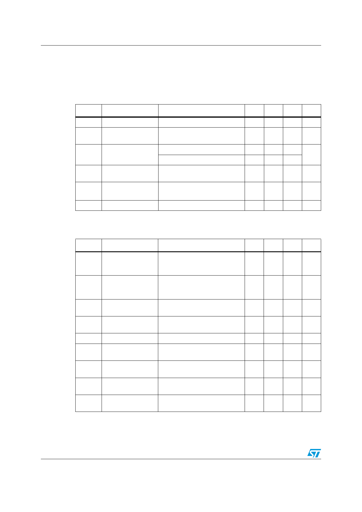
Electrical characteristics
2
Electrical characteristics
VIPER12A-E
TJ = 25 °C, VDD = 18 V, unless otherwise specified
Table 3. Power section
Symbol
Parameter
Test conditions
Min Typ Max Unit
BVDSS Drain-source voltage ID = 1 mA; VFB = 2 V
730
V
IDSS
OFF State drain
current
VDS = 500 V; VFB = 2 V;
TJ = 125 °C
0.1 mA
rDS(on)
Static drain-source
ON state resistance
tf
Fall time
ID = 0.2 A ID = 0.2 A;
ID = 0.2 A ID = 0.2 A; TJ = 100 °C
ID = 0.1 A; VIN = 300 V (1)
(See Figure 9 on page 13)
27 30
Ω
54
100
ns
tr
Rise time
ID = 0.2 A; VIN = 300 V (1)
(See Figure 9 on page 13)
50
ns
COSS Drain capacitance
VDS = 25 V
40
pF
1. On clamped inductive load
Table 4. Supply section
Symbol
Parameter
Test conditions
Min Typ Max Unit
IDDch
IDDoff
IDD0
IDD1
Start-up charging
current
100 V ≤ VDS ≤ 400 V;
VDD = 0 V ...VDDon
(See Figure 10 on page 13)
Start-up charging
current in thermal
shutdown
VDD = 5 V; VDS = 100 V
TJ > TSD - THYST
Operating supply
current not switching
IFB = 2 mA
Operating supply
current switching
IFB = 0.5 mA; ID = 50 mA (1)
-1
mA
0
mA
3
5 mA
4.5
mA
DRST
VDDoff
VDDon
Restart duty-cycle
VDD undervoltage
shutdown threshold
VDD start-up
threshold
(See Figure 11 on page 13)
(See Figure 10,
Figure 11 on page 13)
(See Figure 10,
Figure 11 on page 13))
16
%
7
8
9
V
13 14.5 16
V
VDDhyst
VDD threshold
hysteresis
VDDovp
VDD overvoltage
threshold
(See Figure 10 on page 13)
5.8 6.5 7.2 V
38 42
46
V
1. These test conditions obtained with a resistive load are leading to the maximum conduction time of the
device.
4/21
Doc ID 11977 Rev 2
Share Link: 