VSC8201 гғҮгғјгӮҝгӮ·гғјгғҲгҒ®иЎЁзӨәпјҲPDFпјү - Vitesse Semiconductor
йғЁе“Ғз•ӘеҸ·
гӮігғігғқгғјгғҚгғігғҲиӘ¬жҳҺ
гғЎгғјгӮ«гғј
VSC8201
Vitesse Semiconductor

VSC8201 Datasheet PDF : 21 Pages
| |||
VSC8201DL
Design for Signal Integrity
Many high speed signal pins on the VSC8201 have rise/fall times of the order of 0.7 to 2.4 ns. Because of these fast rise/fall times, inter-
connects should be treated as transmission lines rather than simple lumped element connections. Use of transmission lines with a basic
understanding of line matching will reduce signal reflections which degrades overall performance of the part.
Theory
In order to apply correct impedance matching/termination techniques it is important to know about the types of interconnects used on the
PC board. There are 2 kinds of traces on a PC Board.
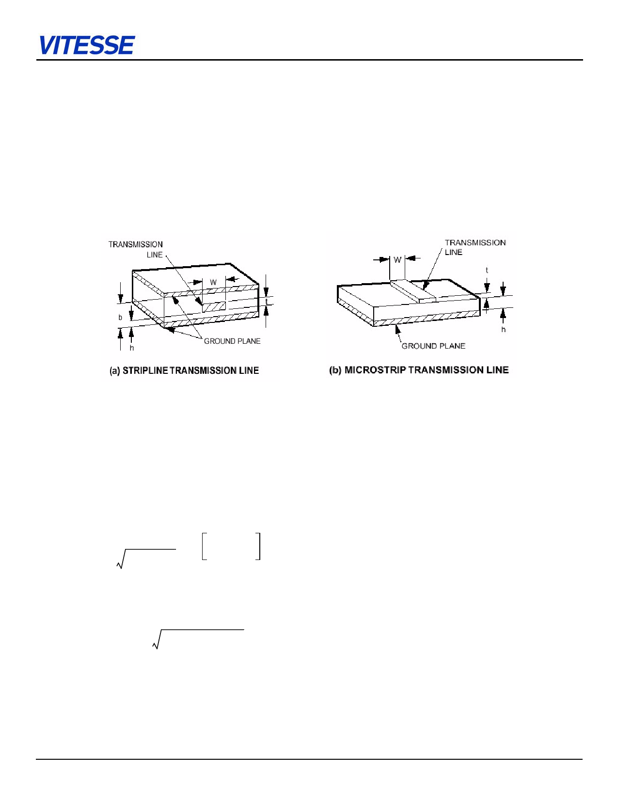
вҖў In case the signal transmission line is sandwiched between the dielectric material of the board and 2 conducting planes it is called a
stripline.
Figure 6: Transmission Lines
вҖў A signal transmission line that has one side open to air and dielectric material and a conducting plane beneath it, is called a micros-
trip.
Оө Impedance of a transmission line is determined by the relative dielectric constant r of the PC board material, thickness of the dielectric
h w t ,the width and the thickness of the transmission line .
Characteristic impedance of the microstrip is calculated using the approximation:
Zo
=
-----------8---7----------- вӢ… ln
Оөr + 1.41
-5---.--9---8----вӢ…---h---
0.8w + t
в„Ұ
The propagation delay for the microstrip is:
tpd = (85) вӢ… 0.475Оөr + 0.67 ps/ft
Rev. 1.6.3 - 9/29/04
VITESSE - CONFIDENTIAL & PROPRIETARY - DO NOT COPY WITHOUT PERMISSION
- Page 7 of 21 -
Share Link: