XE1202A データシートの表示(PDF) - Semtech Corporation
部品番号
コンポーネント説明
メーカー
XE1202A Datasheet PDF : 32 Pages
| |||
XE1202A TrueRF™
4.1.3 RSSI
When enabled, this function provides an RSSI (Received Signal Strength Indication) based on the signal at the
output of the base-band filter. To enable the RSSI function, the bit “RTParam_RSSI” should be set to “1” (see the
Configuration register section below). When enabled, the status of the RSSI is a 2-bit word stored in register
“DataOut_RSSI”, which can be read via the serial control interface. The contents of the register are defined in
Table 6 below, where VRFFIL is the differential amplitude of the equivalent input RF signal when the receiver is
operated in A-mode. The thresholds VTHRi are the thresholds at the output of the base-band filter divided by the
gain between the input of the receiver and this output.
DataOut_RSSI
00
01
10
11
Description
VRFFIL ≤ VTHR1
VTHR1 < VRFFIL ≤ VTHR2
VTHR2 < VRFFIL ≤ VTHR3
VTHR3 < VRFFIL
Table 6: RSSI status description
Two ranges, each of three VTHRi thresholds are defined and selected via the setting of the register
“RTParam_RSSR”, to provide an overall RSSI range of typically 25 dB.
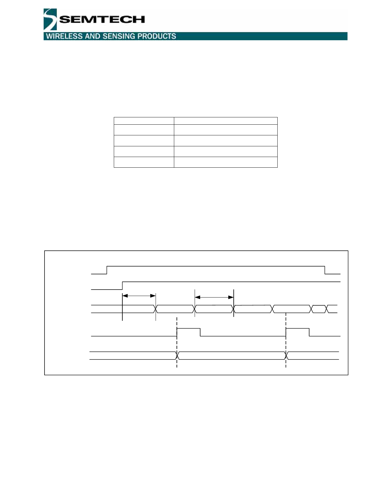
The timing diagram of an RSSI measurement is illustrated by Figure 3 below. When the RSSI function has been
activated the signal strength is periodically measured and the result is stored in the register “DataOut_RSSI” at
each rising edge of DATAIN. TS_RS is the wake-up time required after the function has been enabled to ensure
that a valid reading of RSSI is obtained. For a proper operation, the pulse length on DATAIN has to be higher than
8µs.
RTParam_RSSI
/en
RSSI_out
(internal signal)
datain
DtaOut_RSSI
TS_RS
TS_RSM
xxx
val1
val2
val3
val4
0
xxx
val1
val4
Figure 3: RSSI measurement timing diagram
For applications where a valid RSSI reading is required within as short a time frame as possible, enabling the RSSI
during receiver mode 010 instead of 100 (see the definition of TS_RS in Table 4) allows a valid RSSI within 1 ms of
valid data being received.
4.1.4 Frequency Error Indicator - FEI
When enabled, this function provides an indication of the frequency error of the local oscillator compared with the
received carrier frequency. For guaranteed operation of the FEI function, the following two conditions should be
satisfied.
© Semtech 2006
11
www.semtech.com
Share Link: 