XE1202A データシートの表示(PDF) - Semtech Corporation
部品番号
コンポーネント説明
メーカー
XE1202A Datasheet PDF : 32 Pages
| |||
XE1202A TrueRF™
When “RTParam_Bits” is set to “0”, the bit synchronizer is turned off, and DATAOUT is the output of the
demodulator. In this case DCLK is not used and its value is set “low”.
For guaranteed operation of the demodulator, the modulation index, β, of the modulated carrier should meet the
following condition:
β = 2⋅∆f ≥ 2,
BR
where ∆f is the frequency deviation, and BR the bit rate.
Table 5 details typical sensitivity figures for different bit rates, frequency deviations and baseband filter bandwidths:
Bit rate
[kbits/s
]
4.8
9.6
19.2
38.4
76.8
∆f
[kHz]
5
20
10
20
20
40
40
100
100
BW
[kHz]
10
40
20
40
40
200
200
200
200
Sensitivity for 1 % BER
[dBm]
mode A
mode B
-116
-103
-117
-104
-115
-101
-115.5
-102.5
-112.5
-99.5
-109
-97.5
-107
-95
-109
-97.5
-106.5
-95
Table 5: Sensitivity for 1 % BER
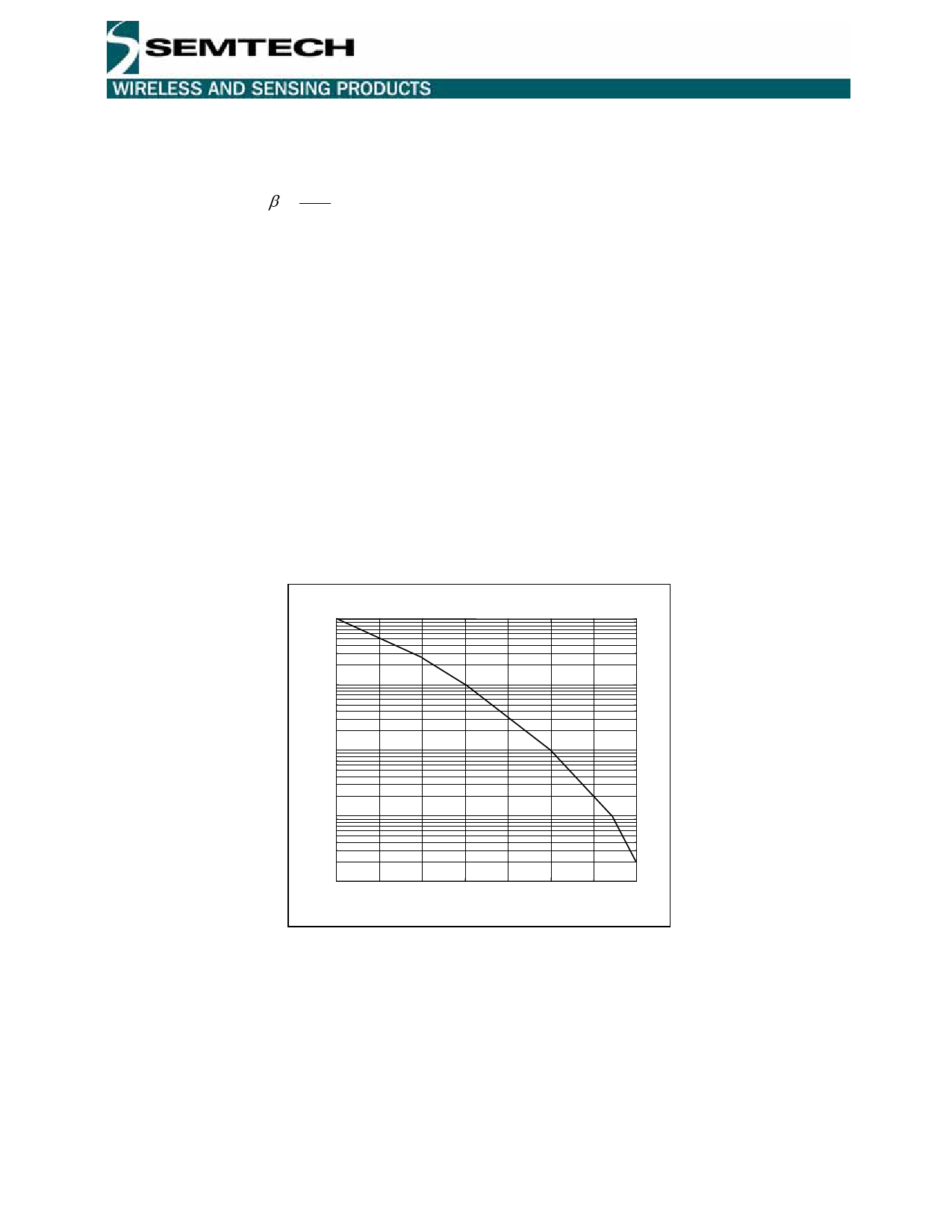
Figure 2 illustrates the typical BER curve under narrowband conditions:
10-2
RX in mode A
10-3
BER
10-4
10-5
10--1616 -115 -114 -113 -112 -111 -110 -109
Pin [dBm]
Figure 2: BER versus Rx input power with BR=4.8 kbits/s, ∆f=5 kHz, BW=10 kHz
4.1.2 Receiver LNA modes
The receiver can be operated in two different modes that provide the highest sensitivity (for reception of weak
signals) or the highest linearity (in areas of strong signals). The receiver mode is determined by the programming of
the “RTParam_Rmode” register (see the Configuration register section below).
A-mode: high sensitivity mode (see RFS parameter)
B-mode: high linearity mode (see IIP3 parameter)
© Semtech 2006
10
www.semtech.com
Share Link: 