XE1205I074TRLF データシートの表示(PDF) - Semtech Corporation
部品番号
コンポーネント説明
メーカー
XE1205I074TRLF
Semtech Corporation

XE1205I074TRLF Datasheet PDF : 48 Pages
| |||
XE1205
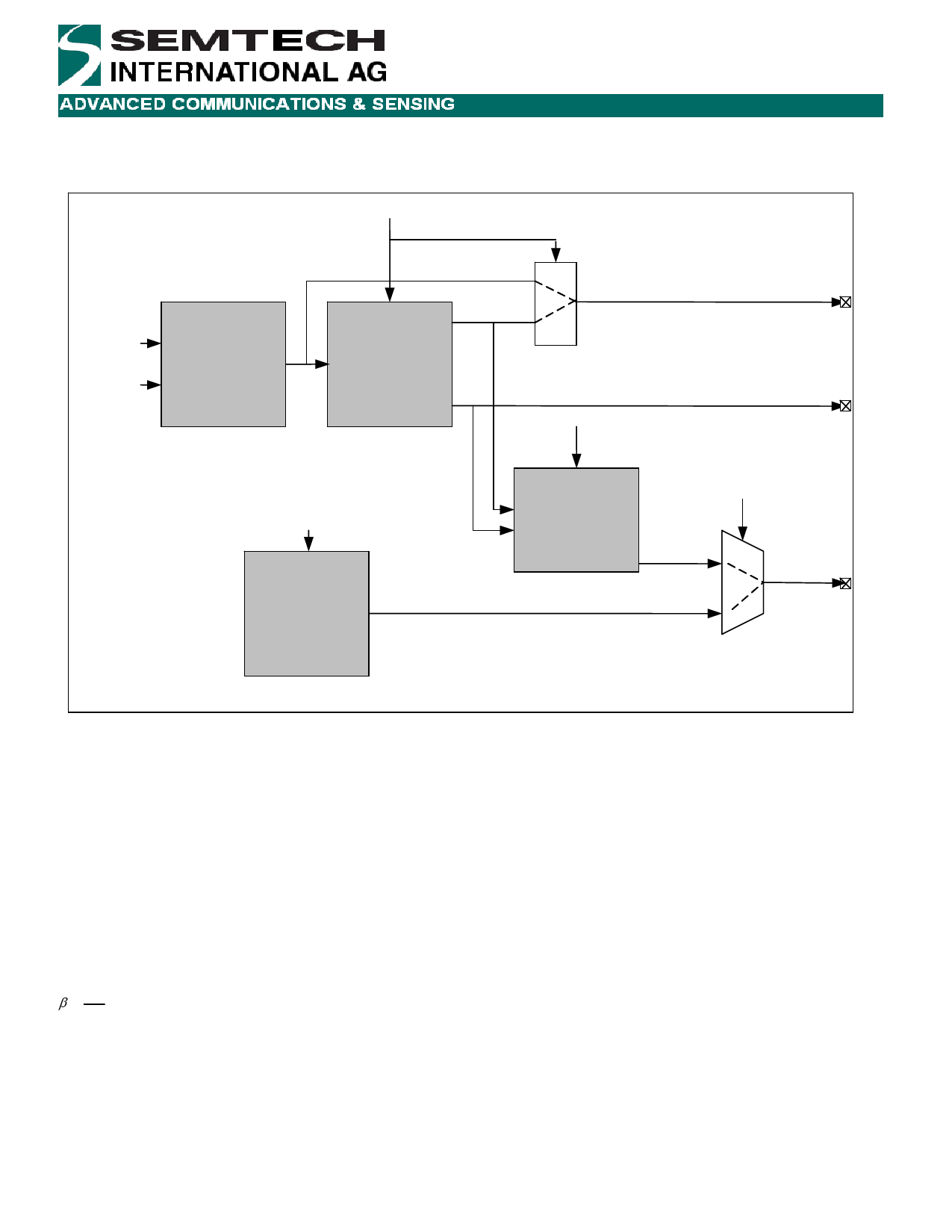
If the bit synchronizer is disabled, the DCLK output is held low and the raw demodulator output appears at DATA.
.
RXParam_Disable_bitsync
I_lim
Q_lim
FSK
DEMODULATOR
data
data
BIT
SYNCHRONIZER
dclk
1
DATA
0
RXParam_Pattern
IRQ_1(DCLK)
RXParam_RSSI
RSSI
PATTERN
MATCHING
IRQParam_Rx_irq_0(1:0)
pattern
IRQ_0
RSSI_irq
Figure 2: Receiver chain in continuous mode
5.2.3.1 Demodulator in continuous mode
The demodulator section comprises FSK demodulator, bit synchronizer, and Pattern Recognition blocks.
Data from the FSK baseband limited signals I_lim and Q_lim is first demodulated before passing to the bit synchronizer.
If the end-user application requires direct access to the output of the demodulator, then the RXParam_Disable_bitsync
bit must be set high. In this case the demodulator output is directly connected to the DATA pin and the IRQ_1 pin
(DCLK) is set to low.
For best operation of the demodulator it is recommended the modulation index β of the input signal meets the following
condition:
β
=
2Δf
BR
≥2
where Δf is the frequency deviation and BR the bit rate.
© Semtech 2008
www.semtech.com
9
Share Link: