ADJ35106 データシートの表示(PDF) - Panasonic Corporation
部品番号
コンポーネント説明
メーカー
ADJ35106 Datasheet PDF : 9 Pages
| |||
DJ (ADJ)
RATING
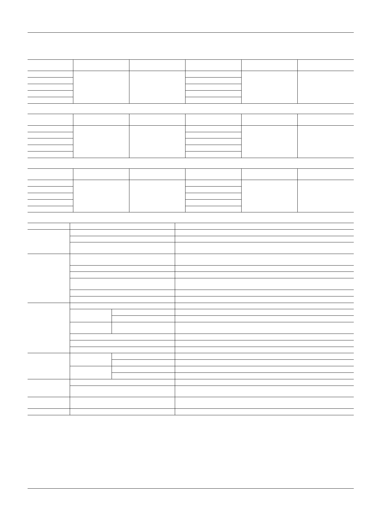
1. Coil data
1) Single side stable
Nominal coil voltage
5V DC
6V DC
12V DC
24V DC
48V DC
Pick-up voltage
(at 20°C 68°F)
75%V or less of nominal
voltage (Initial)
Drop-out voltage
(at 20°C 68°F)
10%V or more of nominal
voltage (Initial)
Coil resistance
[±10%] (at 20°C 68°F)
100Ω
144Ω
576Ω
2,304Ω
9,216Ω
Nominal operating power
Max. applied voltage
(at 20°C 68°F)
250mW
130%V of nominal voltage
2) 1 coil latching
Nominal coil voltage
5V DC
6V DC
12V DC
24V DC
48V DC
Set voltage
(at 20°C 68°F)
70%V or less of nominal
voltage (Initial)
Reset voltage
(at 20°C 68°F)
70%V or less of nominal
voltage (Initial)
Coil resistance
[±10%] (at 20°C 68°F)
167Ω
240Ω
960Ω
3,840Ω
15,360Ω
Nominal operating power
Max. applied voltage
(at 20°C 68°F)
150mW
130%V of nominal voltage
3) 2 coil latching
Nominal coil voltage
5V DC
6V DC
12V DC
24V DC
48V DC
Set voltage
(at 20°C 68°F)
70%V or less of nominal
voltage (Initial)
Reset voltage
(at 20°C 68°F)
70%V or less of nominal
voltage (Initial)
Coil resistance
[±10%] (at 20°C 68°F)
100Ω
144Ω
576Ω
2,304Ω
9,216Ω
Nominal operating power
Max. applied voltage
(at 20°C 68°F)
250mW
130%V of nominal voltage
2. Specifications
Characteristics
Contact
Item
Arrangement
Contact resistance (Initial)
Contact material
Rating
Electrical
characteristics
Mechanical
characteristics
Expected life
Nominal switching capacity (resistive load)
Max. switching power (resistive load)
Max. switching voltage
Max. switching current
Nominal operating power
Min. switching capacity (Reference value)*1
Insulation resistance (Initial)
Breakdown voltage Between open contacts
(Initial)
Between contact and coil
Surge breakdown
voltage*2 (Initial)
Between contact and coil
Temperature rise (coil) (at 70°C 158°F)
Operate time [Set time] (at 20°C 68°F)
Release time [Reset time] (at 20°C 68°F)
Shock resistance
Functional
Destructive
Functional
Vibration resistance
Destructive
Mechanical
Electrical (Resistive load)*3 (at 20 times/min.)
Conditions
Unit weight
Conditions for operation, transport and storage*4
Specifications
1 Form C, 1 Form A, 1 Form B, 1 Form A 1 Form B, 2 Form C, 2 Form A, 2 Form B
Max. 100 mΩ (By voltage drop 6 V DC 1A)
AgSnO2 type (1 Form C, 1 Form A, 1 Form B),
Au-flashed AgSnO2 type (1 Form A 1 Form B, 2 Form C, 2 Form A, 2 Form B)
16 A 250V AC (1 Form C, 1 Form A, 1 Form B),
10 A 250V AC (2 Form C, 2 Form A, 2 Form B, 1 Form A 1 Form B)
4,000 V A
250V AC
16 A (1 Form C, 1 Form A, 1 Form B),
10 A (1 Form A 1 Form B, 2 Form C, 2 Form A, 2 Form B)
150mW (1 coil latching), 250mW (Single side stable, 2 coil latching)
100mA 5 V DC
Min. 1,000MΩ (at 500V DC) Measurement at same location as “Breakdown voltage” section.
1,000 Vrms for 1min. (Detection current: 10mA.)
4,000 Vrms for 1min. (Detection current: 10mA.)
Min. 10,000 V
Max. 55°C (By resistive method, nominal voltage applied to the coil, max. switching current.)
Max. 20 ms [20 ms] (Nominal voltage applied to the coil, excluding contact bounce time.)
Max. 20 ms [20 ms] (Nominal voltage applied to the coil, excluding contact bounce time.)
Min. 200 m/s2 (Half-wave pulse of sine wave: 11 ms; detection time: 10µs.)
Min. 1,000 m/s2 (Half-wave pulse of sine wave: 6 ms.)
10 to 55 Hz at double amplitude of 2 mm (Detection time: 10µs.)
10 to 55 Hz at double amplitude of 3 mm
Min. 5×10⁶ (at 180 times/min.)
Min. 105 (at 16A 250V AC): 1 Form C, 1 Form A, 1 Form B
Min. 105 (at 10A 250V AC): 2 Form C, 2 Form A, 2 Form B, 1 Form A 1 Form B
Ambient temperature: –40°C to +70°C –40°F to +158°F
Humidity: 5 to 85% R.H. (Not freezing and condensing at low temperature)
Approx. 14 g .49 oz
Notes: *1. This value can change due to the switching frequency, environmental conditions, and desired reliability level, therefore it is recommended to check this with the
actual load.
*2. Wave is standard shock voltage of ±1.2×50µs according to JEC-212-1981
*3. In order to obtain the full rated life cycles, the relay should be properly vented by removing the vent nib. More detail, please look at caution for NOTES.
*4. The upper limit of the ambient temperature is the maximum temperature that can satisfy the coil temperature rise value. Refer to Usage, transport and storage
conditions in NOTES.
ASCTB176E 201202-T
Panasonic Corporation Automation Controls Business Unit industrial.panasonic.com/ac/e/
Share Link: 