FSFR1800HSL データシートの表示(PDF) - Unspecified
部品番号
コンポーネント説明
メーカー
FSFR1800HSL Datasheet PDF : 16 Pages
| |||
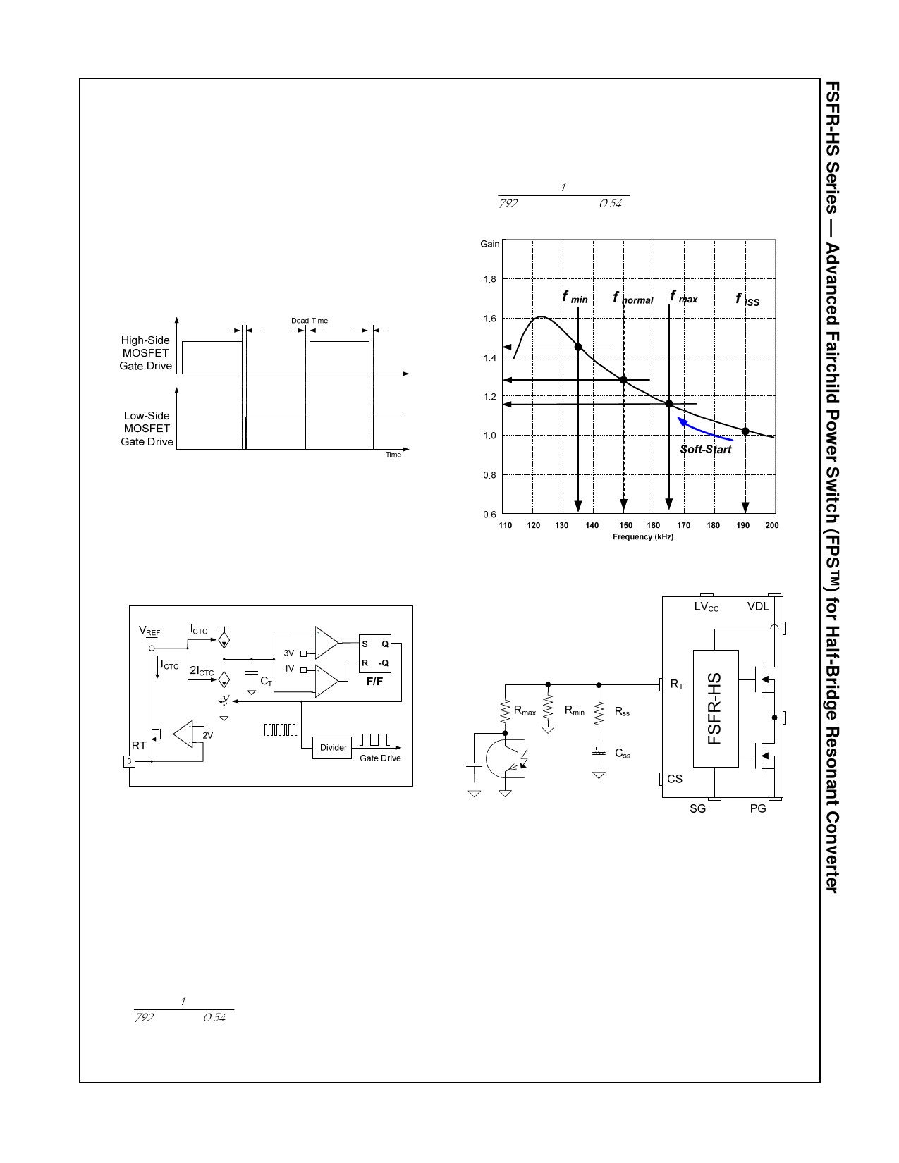
Functional Description
1. Basic Operation: FSFR-HS series is designed to drive
high-side and low-side MOSFETs complementarily with
50% duty cycle. A fixed dead time of 350 ns is introduced
between consecutive transitions, as shown in Figure 18.
Once LVCC is higher than LVCC,START = 12.5 V, the IC
starts to operate, generates the low-side gate signal, and
drives the low-side MOSFET. The bootstrap diode and
capacitor is charged by the low-side MOSFET’s
operation. After the voltage on HVCC increases up to
HVCC,START, typically 9.2 V, the high-side gate signal is
generated for the MOSFET.
Assuming the saturation voltage of opto-coupler
transistor is 0.2 V, the maximum switching frequency is
determined as:
fmax
=
792
p
×
Rmin
1
||
Rmax
+
0.54 µ
[ Hz ]
(2)
Figure 18. MOSFET Gate Drive Signals
2. Internal Oscillator: FSFR-HS series employs a
current-controlled oscillator, as shown in Figure 19.
Internally, the voltage of the RT pin is regulated at 2 V
and the charging / discharging current for the oscillator
capacitor, CT, is obtained by copying the current flowing
out of the RT pin (ICTC) using a current mirror. Therefore,
the switching frequency increases as ICTC increases.
Figure 20. Resonant Converter Typical Gain Curve
Figure 19. Current-Controlled Oscillator
3. Frequency Setting: Figure 20 shows the typical
voltage gain curve of a resonant converter, where the
gain is inversely proportional to the switching frequency
in the ZVS region. The output voltage can be regulated
by modulating the switching frequency. Figure 21 shows
the typical circuit configuration for the RT pin, where the
opto-coupler transistor is connected to the RT pin to
modulate the switching frequency. The switching
frequency may be controlled from 20 kHz to 500 kHz.
The minimum switching frequency is determined as:
fmin
=
792
p×
1
Rmin
+ 0.54 µ
[ Hz ]
(1)
Figure 21. Frequency Control Circuit
To prevent excessive inrush current and overshoot of
output voltage during startup, the IC needs to increase
the voltage gain of the resonant converter progressively.
Since the voltage gain of the resonant converter is
inversely proportional to the switching frequency, soft-
start is implemented by sweeping down the switching
frequency from an initial high frequency (f I S S ) until the
output voltage is established.
The soft-start circuit is constructed by connecting R-C
series network to the RT pin, as shown in Figure 21.
Initially, the operating frequency is set by the parallel
impedance of RSS and Rmin.
© 2011 Fairchild Semiconductor Corporation
FSFR1800 / FSFR1700-HS • Rev.1.0.1
10
www.fairchildsemi.com
Share Link: 