NCV887720BSTGEVB データシートの表示(PDF) - ON Semiconductor
部品番号
コンポーネント説明
メーカー
NCV887720BSTGEVB
ON Semiconductor

NCV887720BSTGEVB Datasheet PDF : 8 Pages
| |||
NCV887720BSTGEVB
Operational Guidelines
The evaluation board is rated to operate under full load for
input voltage as low as 3.75 V at the input terminal under full
power (less if output current is reduced). Start-Stop
applications use reverse battery protection diodes in front of
the boost converter (Figure 2), so the input source can
operate down to 3.75 V plus a diode drop (i.e ∼4.25 V).
Notes:
1. The IC UVLO (undervoltage lockout) is 4.25 V
for VOUT rising, 3.8 V for VOUT falling (0.45 V
hysteresis).
2. Limit time spent with the power supply operating
at minimum input voltage (equivalent to
VIN = 3.75 V) to avoid overheating the power
semiconductors.
First Time Power-Up:
1. Connect a DC source voltage (15 A capable) set to
a voltage of 13 − 14 V as shown in Figure 1.
2. Connect the DISB TTL control signal as shown in
Figure 1. The initial DISB state should be set to
logic −‘0’.
3. Connect a 2.5 A constant current load on the
output.
4. Decrease the DC input voltage until the PCB VIN
voltage is 5.5 V ±0.5 V.
5. Set the DISB control signal to a TTL high state
(i.e. 5 V).
6. Verify that the unit is regulating at
VOUT = 10.0 V.
7. Reduce the DC input voltage until the PCB
VIN = 3.75 V. Verify that the unit is regulating at
VOUT = 10.0 V.
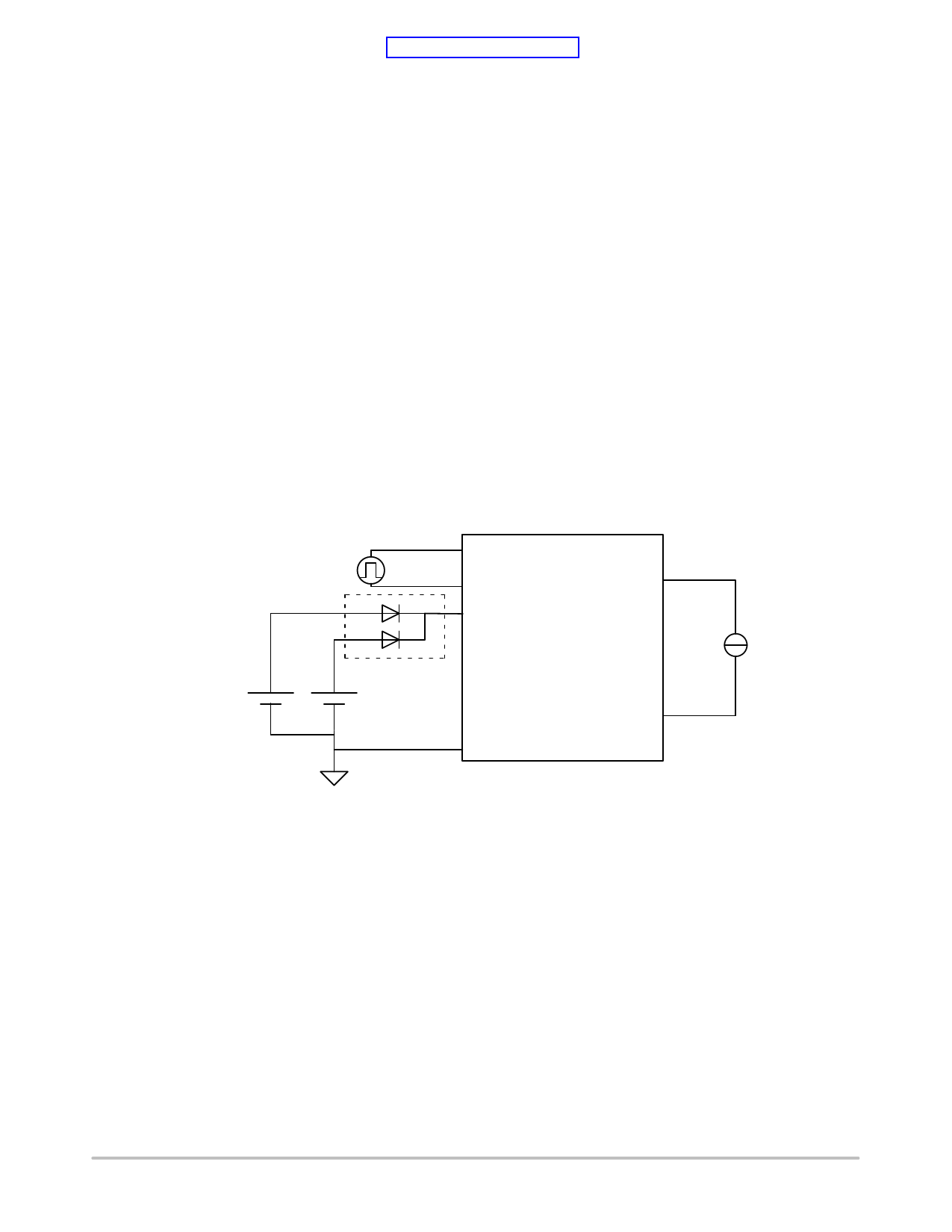
Start-Stop Voltage Transient Test:
1. Connect both DC1 and DC2 input power supplies
as illustrated in Figure 2. Adjust DC2 so that PCB
VIN = 3.75 V for a 2.5 A load.
2. Connect a 2.5 A load on the output. If a load
resistor is used, it is recommended to start from a
DC1 input voltage of 13 − 14 V to avoid
overstressing the PCB boost diode (D1, rated 4 A).
3. Monitor VOUT. Disconnect supply DC1. VOUT
should have a response similar to that of Figure 3.
DISB Command
(TTL)
Reverse Polarity
Protection Diode Harness
DISB
GND
VOUT
VIN NCV887720
10 V / 2.5 A
Evaluation Board
PS2
(30 W capable)
PS1
(15 A capable)
GND
GND
2.5 A
Constant
Current
Load
Figure 2. Evaluation Board Connections
http://onsemi.com
3
Share Link: