CXA2500M データシートの表示(PDF) - Sony Semiconductor
部品番号
コンポーネント説明
メーカー
CXA2500M Datasheet PDF : 11 Pages
| |||
CXA2500M/N
Description of Operation
REF Pin (Pin 1)
A low impedance pin for outputting the internal reference voltage, which is fixed at 0.93V regardless of
supply voltage variation.
LINE OUT Pin (Pin 8)
This output pin outputs signal from any selected source (MIC, Tape or Tuner) to the subsequent stages
such as Dolby NR or power amplifier for further signal processing. It is internally biased at 0.58V so as to
achieve maximum dynamic swing at minimum supply voltage of 1.2V. The change of DC potential at this
pin that may result from any changeover of PB/REC or Tape/Tuner switch was set to be minimum, thus
reducing any potential occurence of switching noise.
REC Out Pin (Pin 10)
This recording driver output pin is internally biased at 1.0V to achieve maximum signal swing at minimum
supply voltage of 1.6V during the recording mode. The REC OUT will be momentally muted during the
changeover of PB/REC or Tape/Tuner modes, so as to prevent mis-recording of any undesired switching
noise. The muting period is determined by the values of R and C at Pins 12 or 13.
AGC TC Pin (Pin 11)
This is the external pin for AGC filter during the MIC Recording mode. The attack time is determined by the
1kΩ resistor inside the IC and the external electrolytic capacitor. The recovery time is determined by both
external resistor and electrolytic capacitor at Pin 11.
Notes on Operation
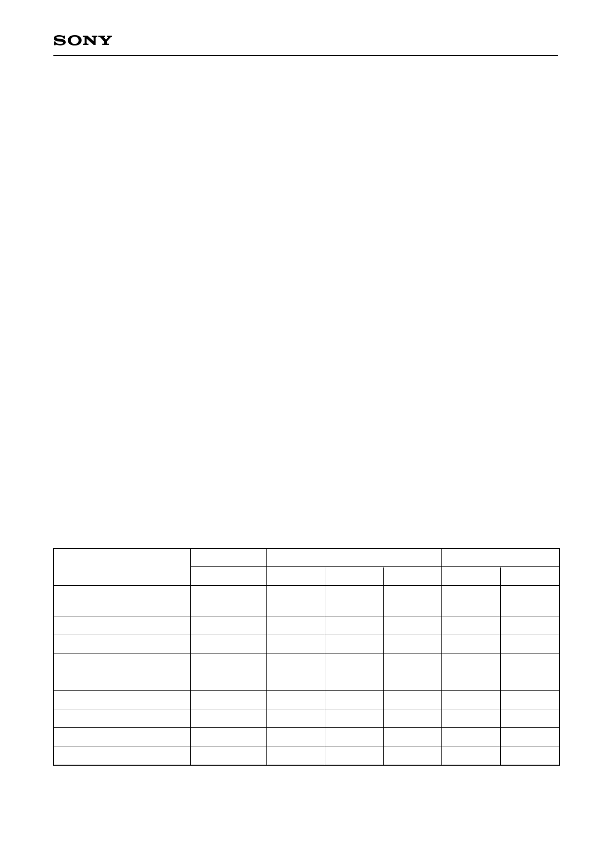
1. The following table shows the potential at Pins 12 and 13 and the associated operating states of the
amplifier. Each of the pins, when at the same potential as Pin 14, has H level, and when at the same
potential as Pin 24, has L level.
System Control Operation Table
Control pins
Amplifier operating state
MIC AMP
AGC DET
GCA
AMP
PB AMP
EQ SWITCH
LINE AMP
REC AMP
Pin 13
Pin 12
Operating
mode
L
Playback
(Normal)
OFF
OFF
OFF
OFF
ON
OFF
ON
OFF
L
FLOAT
Playback
(Metal)
OFF
OFF
OFF
OFF
ON
ON
ON
OFF
H
Tuner
Mode
OFF
OFF
OFF
OFF
OFF
OFF
ON
OFF
H
L, FLOAT
H
MIC
Tuner
Recording Recording
ON
OFF
ON
OFF
ON
OFF
ON
OFF
OFF
OFF
OFF
OFF
ON
ON
ON
ON
–9–
Share Link: 