L295 データシートの表示(PDF) - STMicroelectronics
部品番号
コンポーネント説明
メーカー
L295 Datasheet PDF : 8 Pages
| |||
L295
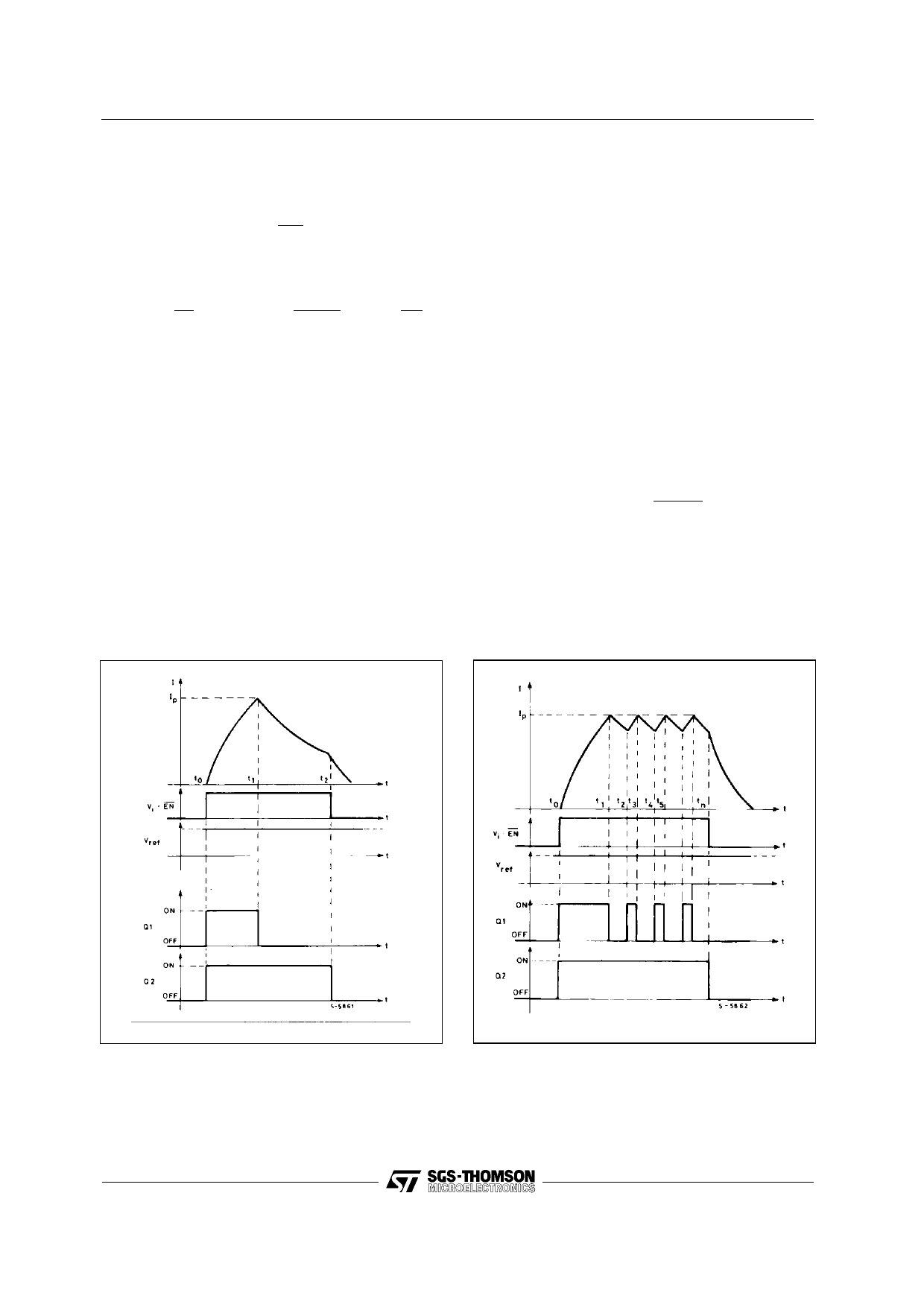
If the oscillator pin (9) is connected to ground the
load current falls to zero as shown in fig. 1.
At this time t2 the channel 1 is disabled, by taking
the inputs Vin1 low and/or EN high, and the output
transistor Q2 is turned off. The load current flows
through D2 and D1 according to the law:
I=(
VB
R1
+ IT2 )
e
− R1 t
L1
−
VB
R1
where VB = VS + VD1 + VD2
IT2 = current value at the time t2.
Fig. 2 in shows the current waveform obtained with
an RC network connected between pin 9 and
ground. From to t1 the current increases as in fig.
1. A difference exists at the time t2 because the
current starts to increase again. At this time a pulse
is produced by the oscillator circuit that resets the
flip.flop, FF1, and switches on the outout transistor,
Q1. The current increases until the drop on the
sensing resistor RS1 is equal to Vref1 (t3) and the
cycle repeats.
SIGNAL WAVEFORMS
Figure 1. Load current waveform with pin 9
connected to GND.
The switching frequency depends on the value R
and C, as shown in fig. 4 and must be chosen in
the range 10 to 30 KHz.
It is possible with external hardware to change the
reference voltage Vref in order to obtain a high peak
current Ip and a lower holding current Ih (see fig. 3).
The L295 is provided with a thermal protection that
switches off all the output transistors when the
junction temperature exceeds 150°C. The pres-
ence of a hysteresis circuit makes the IC work again
aftera fall of the junction temperature of about
20°C.
The analog input pins (Vref1 , Vref2) can be left open
or connected to Vss; in this case the circuit works
with an internal reference voltage of about 2.5V and
the peak current in the load is fixed only by the value
of Rs:
Ip =
2.5
RS
Figure 2. Load current waveform with external
R-C network connected between pin 9 and
ground.
5/8
Share Link: 