MC54F109 データシートの表示(PDF) - Motorola => Freescale
部品番号
コンポーネント説明
メーカー
MC54F109 Datasheet PDF : 3 Pages
| |||
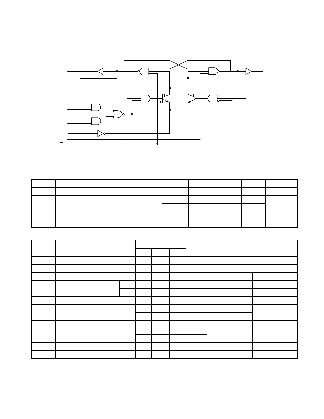
MC54/74F109
LOGIC DIAGRAM (one half shown)
Q
Q
K
J
CP
SD
CD
NOTE:
This diagram is provided only for the understanding of logic operations
and should not be used to estimate propagation delays.
GUARANTEED OPERATING RANGES
Symbol
Parameter
VCC
TA
Supply Voltage
Operating Ambient Temperature Range
IOH
Output Current — High
IOL
Output Current — Low
Min
Typ
Max
Unit
54, 74
4.5
5.0
5.5
V
54
–55
25
125
°C
54
0
25
70
54, 74
–1.0
mA
54, 74
20
mA
DC CHARACTERISTICS OVER OPERATING TEMPERATURE RANGE (unless otherwise specified)
Limits
Symbol
Parameter
Min Typ Max Unit
Test Conditions
VIH
VIL
VIK
VOH
VOL
IIH
IIL
Input HIGH Voltage
Input LOW Voltage
Input Clamp Diode Voltage
Output HIGH Voltage
Output LOW Voltage
Input HIGH Current
Input LOW Current
(J, K and CP Inputs)
2.0
V
Guaranteed Input HIGH Voltage
0.8
V
Guaranteed Input LOW Voltage
–1.2
V
IIN = –18 mA
54, 74 2.5
3.4
V
IOH = –1.0 mA
74 2.7
3.4
V
IOH = –1.0 mA
0.35 0.5
V
IOL = 20 mA
20
µA
VIN = 2.7 V
100
µA
VIN = 7.0 V
VCC = MIN
VCC = 4.50 V
VCC = 4.75 V
VCC = MIN
VCC = MAX
–0.6
mA
VIN = 0.5 V
VCC = MAX
(CD and SD Inputs)
–1.8
mA
IOS
Output Short Circuit Current (Note 2)
–60
–150
mA
VOUT = 0 V
ICC
Power Supply Current
11.7
17
mA
VCP = 0 V
NOTES:
1. For conditions shown as MIN or MAX, use the appropriate value specified under guaranteed operating ranges.
2. Not more than one output should be shorted at a time, nor for more than 1 second.
VCC = MAX
VCC = MAX
FAST AND LS TTL DATA
4-43
Share Link: 