AN8007 データシートの表示(PDF) - Panasonic Corporation
部品番号
コンポーネント説明
メーカー
AN8007 Datasheet PDF : 7 Pages
| |||
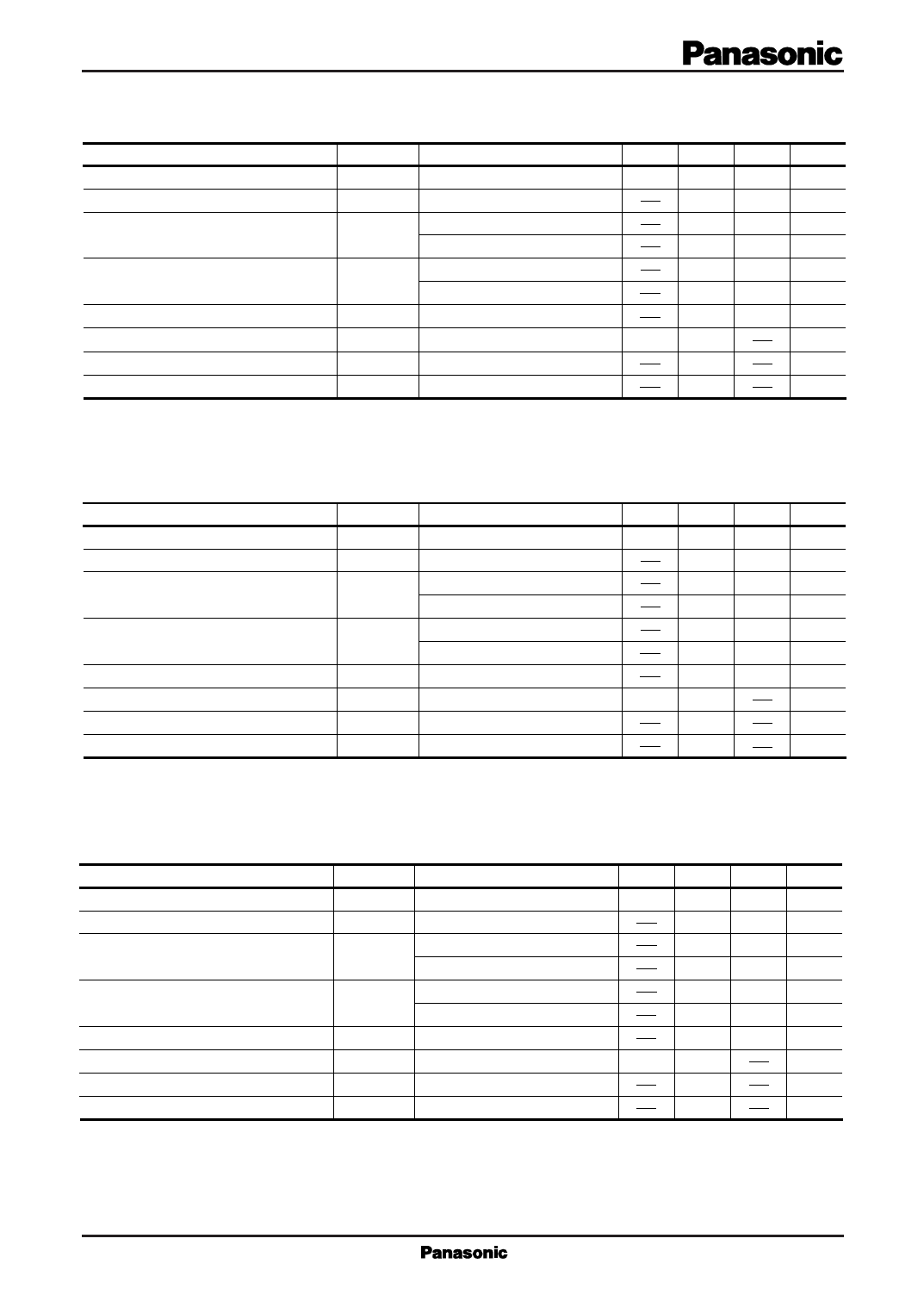
s Electrical Characteristics (Ta=25˚C)
· AN8003/AN8003M (3V Type)
Parameter
Symbol
Condition
min typ max Unit
Output voltage
Line regulation
Load regulation
VO
REGIN
REGL
Tj=25˚C
VI=3.5 to 9V, Tj=25˚C
IO=1 to 40mA, Tj=25˚C
IO=1 to 50mA, Tj=25˚C
2.88
3 3.12
V
3
50 mV
9
25 mV
15
30 mV
Minimum I/O voltage difference
VDIF (min.)
VI=2.9V, IO=20mA, Tj=25˚C
VI=2.9V, IO=50mA, Tj=25˚C
0.07 0.2
V
0.12 0.3
V
Bias current
Ripple rejection ratio
Output noise voltage
Output voltage temperature coefficient
Ibias
RR
Vno
∆VO/Ta
IO=0mA, Tj=25˚C
VI=4 to 6V, f=120Hz
f=10Hz to 100kHz
Tj=–30 to+125˚C
0.6
58
70
70
0.15
1 mA
dB
µV
mV/˚C
Note1) The specified condition Tj=25˚C means that the test should be conducted with each test time reduced (within 10ms) so that
the drift in characteristic value due to a temperature rise at chip junction can be ignored.
Note2) Unless otherwise specified, VI=4V, IO=20mA, CO=10µF
· AN8035/AN8035M (3.5V Type)
Parameter
Symbol
Condition
min typ max Unit
Output voltage
Line regulation
Load regulation
VO
REGIN
REGL
Tj=25˚C
VI=4 to 9.5V, Tj=25˚C
IO=1 to 40mA, Tj=25˚C
IO=1 to 50mA, Tj=25˚C
3.36
3.5 3.64
V
3.5
50 mV
10
30 mV
20
40 mV
Minimum I/O voltage difference
VDIF (min.)
VI=3.4V, IO=20mA, Tj=25˚C
VI=3.4V, IO=50mA, Tj=25˚C
0.07 0.2
V
0.12 0.3
V
Bias current
Ripple rejection ratio
Output noise voltage
Output voltage temperature coefficient
Ibias
RR
Vno
∆VO/Ta
IO=0mA, Tj=25˚C
VI=4.5 to 6.5V, f=120Hz
f=10Hz to 100kHz
Tj=–30 to+125˚C
0.6
57
69
75
0.2
1 mA
dB
µV
mV/˚C
Note1) The specified condition Tj=25˚C means that the test should be conducted with each test time reduced (within 10ms) so that
the drift in characteristic value due to a temperature rise at chip junction can be ignored.
Note2) Unless otherwise specified, VI=4.5V, IO=20mA, CO=10µF
· AN8004/AN8004M (4V Type)
Parameter
Symbol
Condition
min typ max Unit
Output voltage
Line regulation
Load regulation
VO
REGIN
REGL
Tj=25˚C
VI=4.5 to 10V, Tj=25˚C
IO=1 to 40mA, Tj=25˚C
IO=1 to 50mA, Tj=25˚C
3.84
4 4.16
V
3.5
50 mV
10
30 mV
20
40 mV
Minimum I/O voltage difference
VDIF (min.)
VI=3.8V, IO=20mA, Tj=25˚C
VI=3.8V, IO=50mA, Tj=25˚C
0.07
0.2
V
0.12
0.3
V
Bias current
Ripple rejection ratio
Output noise voltage
Output voltage temperature coefficient
Ibias
RR
Vno
∆VO/Ta
IO=0mA, Tj=25˚C
VI=5 to 7V, f=120Hz
f=10Hz to 100kHz
Tj=–30 to+125˚C
0.6
56
67
80
0.2
1 mA
dB
µV
mV/˚C
Note1) The specified condition Tj=25˚C means that the test should be conducted with each test time reduced (within 10ms) so that
the drift in characteristic value due to a temperature rise at chip junction can be ignored.
Note2) Unless otherwise specified, VI=5V, IO=20mA, CO=10µF
Share Link: 