CD74HCT139E データシートの表示(PDF) - Harris Semiconductor
部品番号
コンポーネント説明
メーカー
CD74HCT139E Datasheet PDF : 5 Pages
| |||
CD74HC139, CD74HCT139
Switching Specifications Input tr, tf = 6ns (Continued)
PARAMETER
TEST
VCC
SYMBOL CONDITIONS (V)
25oC
-40oC TO
85oC
MIN TYP MAX MIN MAX
-55oC TO
125oC
MIN MAX UNITS
Output Transition Time (Figure 1) tTLH, tTHL CL = 50pF
2
-
-
75
-
95
-
110 ns
4.5
-
-
15
-
19
-
22
ns
6
-
-
13
-
16
-
19
ns
Power Dissipation
Capacitance, (Notes 5, 6)
CPD
-
5
-
55
-
-
-
-
-
pF
Input Capacitance
HCT TYPES
Propagation Delay
CIN
-
-
-
-
10
-
10
-
10
pF
A0, A1 to Outputs
E to Outputs
Select to Output
Enable to Output
Output Transition Time
(Figure 2)
tPLH,
CL = 50pF
4.5
-
-
34
-
43
-
51
ns
tPHL
tPLH,
CL = 50pF
4.5
-
-
34
-
43
-
51
ns
tPHL
tPLH, tPHL CL = 15pF
5
-
14
-
-
-
-
-
ns
tPLH, tPHL CL = 15pF
5
-
14
-
-
-
-
-
ns
tTLH, tTHL CL = 50pF
4.5
-
-
15
-
19
-
22
ns
Power Dissipation
Capacitance, (Notes 5, 6)
CPD
-
5
-
59
-
-
-
-
-
pF
Input Capacitance
CIN
-
-
-
-
10
-
10
-
NOTES:
5. CPD is used to determine the dynamic power consumption, per decoder/demux.
6. PD = VCC2 fi (CPD + CL) where: fi = Input Frequency, CL = Output Load Capacitance, VCC = Supply Voltage.
10
pF
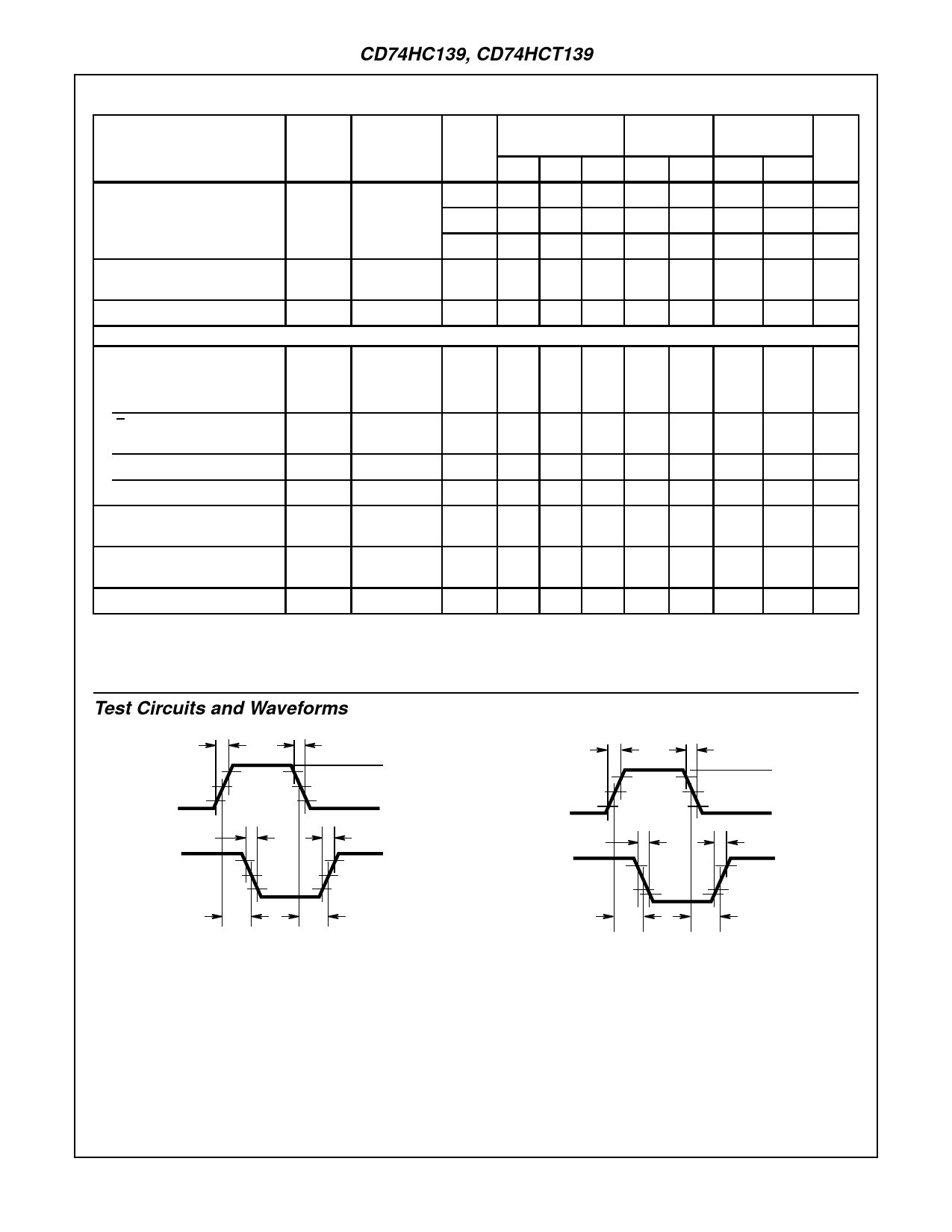
Test Circuits and Waveforms
tr = 6ns
INPUT
90%
50%
10%
tf = 6ns
VCC
GND
tTHL
INVERTING
OUTPUT
tPHL
tTLH
90%
50%
10%
tPLH
FIGURE 1. HC AND HCU TRANSITION TIMES AND PROPAGA-
TION DELAY TIMES, COMBINATION LOGIC
tr = 6ns
INPUT
2.7V
1.3V
0.3V
tf = 6ns
3V
GND
tTHL
INVERTING
OUTPUT
tPHL
tTLH
90%
1.3V
10%
tPLH
FIGURE 2. HCT TRANSITION TIMES AND PROPAGATION
DELAY TIMES, COMBINATION LOGIC
5
Share Link: 