CS61304A データシートの表示(PDF) - Cirrus Logic
部品番号
コンポーネント説明
メーカー
CS61304A Datasheet PDF : 32 Pages
| |||
CS61304A
CS61304A
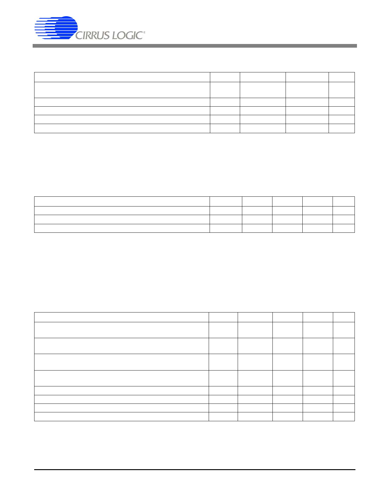
ABSOLUTE MAXIMUM RATINGS
Parameter
Symbol
Min
Max
Units
DC Supply (referenced to RGND=TGND=0V)
RV+
TV+
-
6.0
V
-
(RV+) + 0.3 V
Input Voltage, Any Pin
(Note 1) Vin
RGND-0.3 (RV+) + 0.3 V
Input Current, Any Pin
(Note 2) Iin
-10
10
mA
Ambient Operating Temperature
TA
-40
85
°C
Storage Temperature
Tstg
-65
150
°C
WARNING:Operations at or beyond these limits may result in permanent damage to the device.
Normal operation is not guaranteed at these extremes.
Notes: 1. Excluding RTIP, RRING, which must stay within -6V to (RV+) + 0.3V.
2. Transient currents of up to 100 mA will not cause SCR latch-up. Also TTIP, TRING, TV+ and TGND
can withstand a continuous current of 100 mA.
RECOMMENDED OPERATING CONDITIONS
Parameter
Symbol Min
Typ
Max Units
DC Supply
(Note 3) RV+, TV+ 4.75
5.0
5.25
V
Ambient Operating Temperature
TA
-40
25
85
°C
Power Consumption
(Notes 4,5) PC
-
-
350 mW
Notes: 3. TV+ must not exceed RV+ by more than 0.3V.
4. Power consumption while driving line load over operating temperature range. Includes IC and load.
Digital input levels are within 10% of the supply rails and digital outputs are driving a 50 pF
capacitive load.
5. Assumes 100% ones density, 5.25 V, LEN2/1/0=1/1/1, a 100 Ω load and a 1:1.15 transformer.
DIGITAL CHARACTERISTICS (TA = -40°C to 85°C; TV+, RV+ = 5.0V ±5%; GND = 0V)
Parameter
Symbol Min
Typ
Max
High-Level Input Voltage
(Notes 6, 7) VIH
2.0
-
-
PINS 1-4, 17, 18, 23-28
Low-Level Input Voltage
(Notes 6, 7) VIL
-
PINS 1-4, 17, 18, 23-28
-
0.8
High-Level Output Voltage
(Notes 6, 7, 8) VOH
2.4
-
-
IOUT = -400 µA
PINS 6-8, 11, 12, 25
Low-Level Output Voltage
(Notes 6, 7, 8) VOL
-
IOUT = 1.6 mA
PINS 6-8, 11, 12, 23, 25
-
0.4
Input Leakage Current (Except Pin 5)
-
-
±10
Low-Level Input Voltage, PIN 5
VIL
-
-
0.2
High-Level Input Voltage, PIN 5
VIH (RV+) - 0.2
-
-
Mid-Level Input Voltage, PIN 5
(Note 9) VIM
2.3
-
2.7
Notes: 6. In Extended Hardware Mode, pins 17 and 18 are digital inputs. In Host Mode, pin 23 is
an open drain output and pin 25 is a tristate digital output.
7. This specification guarantees TTL compatibility (VOH = 2.4V @ IOUT = -40µA).
8. Output drivers will drive CMOS logic levels into a CMOS load.
9. As an alternative to supplying a 2.3-to-2.7V input, this pin may be left floating.
Units
V
V
V
V
µA
V
V
V
2
DSD1S5165P6PF21
Share Link: 