CS61304A データシートの表示(PDF) - Cirrus Logic
部品番号
コンポーネント説明
メーカー
CS61304A Datasheet PDF : 32 Pages
| |||
THEORY OF OPERATION
Key Enhancements of the CS61304A Relative
to the LXT304A
• 12.5% Lower Power Consumption,
• 50 mARMS transmitter short-circuit current
limiting for E1 (per OFTEL OTR-001),
• Optional AMI, B8ZS, HDB3 encoder/de-
coder or external line coding support,
• Receiver AIS (unframed all ones) detection,
• Improved receiver Loss of Signal handling
(LOS set at power-up, reset upon receipt of
3 ones in 32 bit periods with no more than
15 consecutive zeros),
• Transmitter TTIP and TRING outputs are
forced low when TCLK is static,
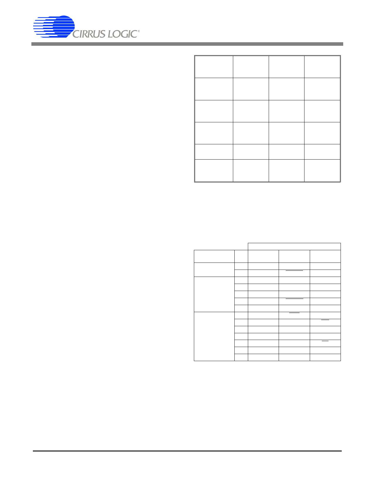
Introduction to Operating Modes
The CS61304A supports three operating modes
which are selected by the level of the MODE pin
as shown in Tables 1 and 2, Figure 7, and Figures
A1-A3 of the Applications section.
The modes are Hardware Mode, Extended Hard-
ware Mode, and Host Mode. In Hardware and
Extended Hardware Modes, discrete pins are used
to configure and monitor the device. The Ex-
tended Hardware Mode provides a parallel chip
select input which latches the control inputs al-
lowing individual ICs to be configured using a
common set of control lines. In the Host Mode,
an external processor monitors and configures the
device through a serial interface. There are thir-
teen multi-function pins whose functionality is
determined by the operating mode. (see Table 2).
CS61304A
CS61304A
Control
Method
MODE
Pin
Level
Line
Coding
AIS
Detection
Driver
Performance
Monitor
Hardware
Mode
Control
Pins
<0.2 V
External
No
Yes
Extended
Host
Hardware
Mode
Mode
Control Pins Serial
with Parallel Interface
Chip Select
Floating or >(RV+)-0.2
2.5 V
V
Internal-
AMI, B8ZS,
or HDB3
Yes
External
No
No
Yes
Table 1. Differences Between Operating Modes
MODE
FUNCTION
EXTENDED
PIN HARDWARE HARDWARE
TRANSMITTER 3
4
TPOS
TNEG
TDATA
TCODE
6
RNEG
BPV
7
RECEIVER/DPM 11
RPOS
DPM
RDATA
AIS
17
MTIP
RCODE
18 MRING
-
18
-
PCS
23
LEN0
LEN0
24
LEN1
CONTROL
25
LEN2
LEN1
LEN2
26 RLOOP
RLOOP
27 LLOOP
LLOOP
28
TAOS
TAOS
HOST
TPOS
TNEG
RNEG
RPOS
DPM
MTIP
MRING
-
INT
SDI
SDO
CS
SCLK
CLKE
Table 2. Pin Definitions
8
DSD1S5165P6PF21
Share Link: 