ID246PXX データシートの表示(PDF) - Sharp Electronics
部品番号
コンポーネント説明
メーカー
ID246PXX Datasheet PDF : 38 Pages
| |||
SHARP
ID246 SERIES PRODUCT OVERVIEW
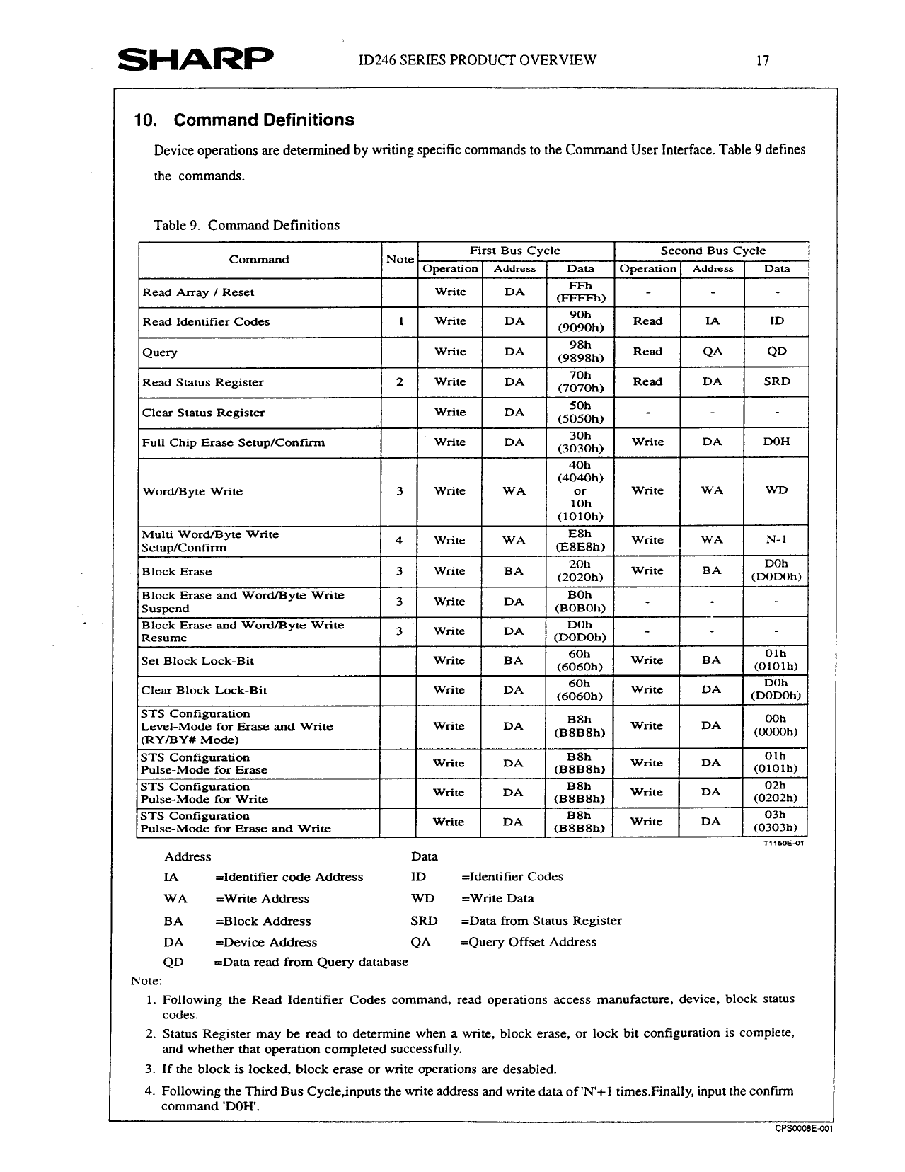
10. Command Definitions
Device operations are determined by writing specific commands to the Command User Interface. Table 9 defines
the commands.
Table 9. Command Definitions
Read Identifier Codes
Word/Byte
Write
Level-Mode
for Erase
(RY/BY# Mode)
STS Configuration
Pulse-Mode
for Erase
STS Configuration
Pulse-Mode
for Write
STS Configuration
Pulse-Mode
for Erase
and Write
and Write
Address
IA
=Identifier
cede Address
write
DA
B8h
(BSBSh)
Write
Write
B8h
DA
(BSBSh)
Write
Write
DA
B8h
(BSBSh)
Write
Data
ID
=IdentiIier
Codes
DA
Olh
(OlOlh)
DA
02h
(0202h)
DA
03h
(0303h)
T115oE-m
WA
=Write Address
WD
=Write Data
BA
=Block Address
SRD
=Data from Status Register
DA
=Device Address
QA
=Quety Offset Address
QD
Note:
=Data read from Query database
1. Following
codes.
the Read Identifier Codes command, read operations access manufacture, device,
2. Status Register may be read to determine when a write, block erase, or lock bit configuration
and whether that operation completed successfully.
3. If the block is locked, block erase or write operations are desabled.
block status
is complete,
4. Following the Third Bus Cycle,inputs the write address and write data of ‘N’+l times.Finally, input the confirm
command ‘DOH’.
CP%008E40
Share Link: 