LX1710-1 データシートの表示(PDF) - Microsemi Corporation
部品番号
コンポーネント説明
メーカー
LX1710-1 Datasheet PDF : 18 Pages
| |||
LXE1710 EVALUATION BOARD
USER GUIDE
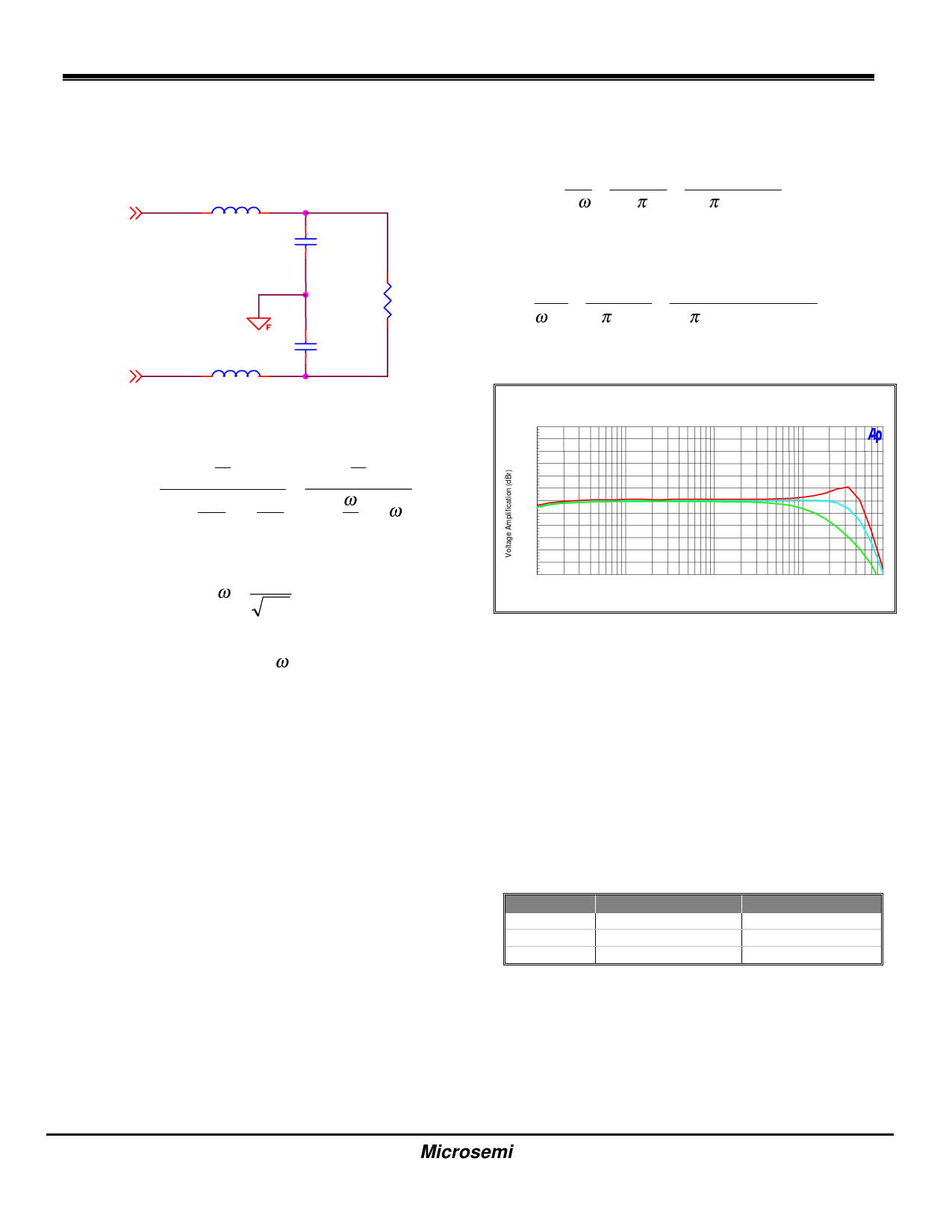
evaluation board is a second order, LC type filter as
shown below. Tradeoffs between performance and
component cost must be considered when determining
the complexity or type of filter selected.
OUT+
L 15µH
C
0.68µF
R
OUT-
L 15µH
C
0.68µF
Its Laplace Transform function is:
S
S
H(S) =
S2 +
C
1 S+
1
=
S
2
+
C
ωS
+ω
2
RC LC
Q
Where
ω= 1
LC
Q = RCω
The Class-D amplifier evaluation board design has a
pass-band of 20Hz to 20kHz to support the audio
frequency range and is configured to utilize a switching
or oscillator frequency fs = 500kHz. Depending on the
application, this oscillator frequency may be adjusted
(see section on Oscillator Configuration) to optimize
amplifier performance or modified for other
considerations such as EMI effects. Further
requirements of the filter are that the pass band
attenuation of switching frequency fs should be lower
than 40dB and the corner frequency of the LC filter
should be set higher than 20kHz to avoid attenuating
audio signals in the desired audio band by more than
1dB. A speaker DC impedance o '-
C =
50kHz corner frequency are defined for the evaluation
board.
The Q (selectivity factor or ratio of the center
frequency divided by the bandwidth) of the filter must
also be considered when designing a filter. Too high a
Q will result in a boost of the audio signal across the
audio band whereas a low Q will cause too much
attenuation of the signal. A Q value of 0.707 provides
the required audio response and is used in the
calculation below.
C = Q = Q = 0.707 = 0.56µF
Rω R(2πfC) 4(2π )(50000)
C = 0.68µF is used in the EvaluationBoard
To Compute the Inductor Value:
L
=
1
ω 2C
=
1
(2πfC )2 C
=
1
[(2π )(50000)]2(.68µ)
= 14.9µ H
L = 15µH is used in the EvaluationBoard
+15
+12.5
+10
+7.5
+5
+2.5
+0
-2.5
-5
-7.5
-10
-12.5
-15
10 20
LXE1710 Evaluation Board
Frequency Response
50 10 20
50
1k 2k
Frequency (Hz)
5k 10 20
k
k
50 80
kk
Frequency response of the audio amplifier was
$
"
)
,! - $-
+ - -
"
"
' .
! - ,
) "
+ )/ .
–4dB
attenuation respectively. Therefore, to improve
frequency response performance for other loads, the
value of Q must be increased/decreased by changing
the capacitor. Since a different value C will affect the
corner frequency, values for L and C must be
recalculated. Below are recommended inductor and
capacitor values for 2
,
-
single stage LC filter design.
Capacitor C (µF)
1.0
0.68
0.47
Filter Component Values
Inductor L (µH)
10
15
22
Please note: These recommended values are guidelines
for speaker loads. Actual speakers have varying
impedances, which may require revised filter calculations
and optimization. Furthermore, your application may have
different design goals than those chosen for the LX1710
evaluation board.
Copyright © 2000
Rev. 1.1, 2000-12-01
Microsemi
Linfinity Microelectronics Division
11861 Western Avenue, Garden Grove, CA. 92841, 714-898-8121, Fax: 714-893-2570
Page 10
Share Link: 