NJM2211M データシートの表示(PDF) - Japan Radio Corporation
部品番号
コンポーネント説明
メーカー
NJM2211M Datasheet PDF : 10 Pages
| |||
NJM2211
■ DESIGN EQUATIONS
See Figure 1 for Definitions of Components.
1. VCO Center Frequency, f0 :
f0
(Hz)
=
1
R0C0
2. Internal Reference Voltage, VR (measured at pin 10) :
VR
=
+ VS
2
−
650mV
3. Loop Lowpass Filter Time Constant, τ :
τ=R1C1
4. Loop Damping, ξ :
ξ
=
C0
C1
1
4
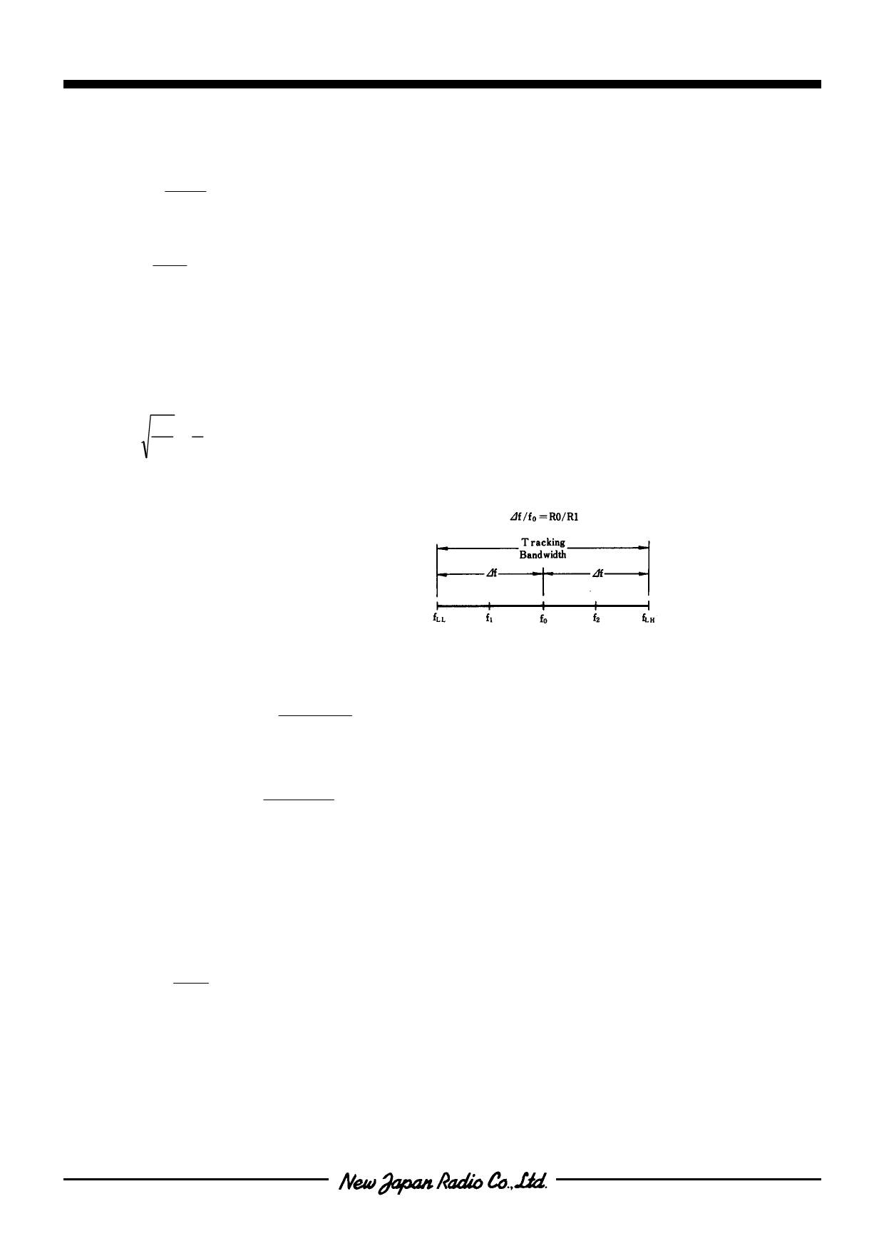
5. Loop Tracking Bandwidth, ±∆f/f0 :
∆f/f0 =R0 / R1
6. FSK Date Filter Time Constant, τF :
τF=RFCF
7. Loop Phase Detector Conversion Gain, Kφ :
(Kφ is the differential DC voltage across pins 10 and 11, per unit of phase error at phase-detector input) :
Kφ
(in
volts
per
radian)
=
(−
2)(VREF
π
)
8. VCO conversion Gain, K0, is the amount of change in VCO frequency per unit of DC voltage change at pin 11 :
K0
(in Hertz
per
volt)
=
−1
C0R1VREF
9. Total Loop Gain Kτ :
KT (in radians per second per volt =2πKφK0
=4 / C0R1
10. Peak Phase-Detector Current, IA :
IA (mA)
=
VREF
25
-6-
Ver.2003-12-09
Share Link: 