NJM2211M データシートの表示(PDF) - Japan Radio Corporation
部品番号
コンポーネント説明
メーカー
NJM2211M Datasheet PDF : 10 Pages
| |||
NJM2211
■ APPLICATIONS
FSK Decoding
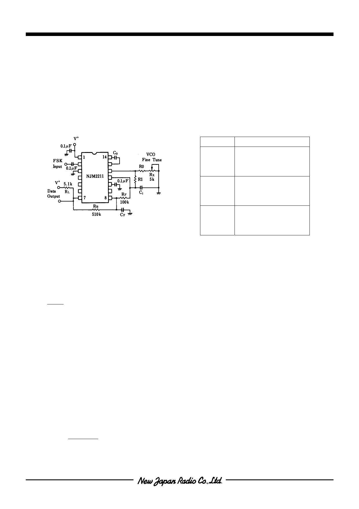
Figure 2 shows the basic circuit connection for FSK decoding. With reference to Figures 1 and 2, the functions of
external components are defined as follows : R0 and C0 set the PLL center frequency. R1 sets the system bandwidth,
and C1 sets the loop filter time constant and the loop damping factor. CF and RF from a one pole post-detection filter for
the FSK data output. The resistor RB (=510kΩ) from pin 7 to pin 8 introduces positive feedback across FSK comparator
to facilitate rapid transition between output logic states.
Recommended component values for some of the most commonly used FSK bauds are given in Table 1.
Figure 2. FSK Decoding
Table 1. Recommended Value for FSK
(Ref. Fig. 2)
FSK Band
Component Values
300 Band C0=0.039µF CF=0.005µF
F1 =1070Hz C1=0.01µF R0=18kΩ
f2 =1270Hz R1=100kΩ
300 Band C0=0.022µF CF=0.005µF
f1=2025Hz C1=0.0047µF R0=18kΩ
f2=2225Hz R1=200kΩ
1200 Band C0=0.027µF CF=0.0022µF
f1=1200Hz C1=0.01µF R0=18kΩ
f2=2200Hz R1=30kΩ
Design Instructions
The circuit of Figure 2 can be tailored for any FSK decoding application by the choice of five key circuit components ;
R0, R1, C0, C1 and CF. For a given set of FSK mark and space frequencies. f1 and f2, these parameters can be
calculated as follows :
1. Calculate PLL center frequency, f0
f0
=
f1
+ f2
2
2. Chose a value of timing resistor R0 to be in the range of 10kΩ to 100kΩ. This choice is arbitary. The recommended
value is R0 ≅ 20kΩ. The final value of R0 is normally fine-tuned with the series potentiometer, Rx.
3. Calculate value of C0 from Design Equation No.1 or from Typical Performance Characteristics :
C0=1 / R0f0
4. Calculate R1 to give a ∆f equal to the mark-space deviation :
R1=R0 [f0 / (f1 - f2)]
5. Calculate C1 to set loop damping. (See Design Equation No.4.)
Normally, ξ ≈ 1 / 2 is recommended
Then :C1=C0 / 4 for ξ =1 / 2
6. Calculate Data Filter Capacitance, CF :
For RF=100kΩ. RB=510kΩ, the recommended value of CF is :
CF (in
µF)
=
3
Band Rate
Note : All calculated component values except R0 can be rounded off to the nearest standard value, and R0 can be varied to fine-tune center
frequency through a series potentiometer, Rx (see Figure 2).
Ver.2003-12-09
-7-
Share Link: 