IW4017B データシートの表示(PDF) - Estek Electronics Co. Ltd
部品番号
コンポーネント説明
メーカー
IW4017B Datasheet PDF : 6 Pages
| |||
IW4017B
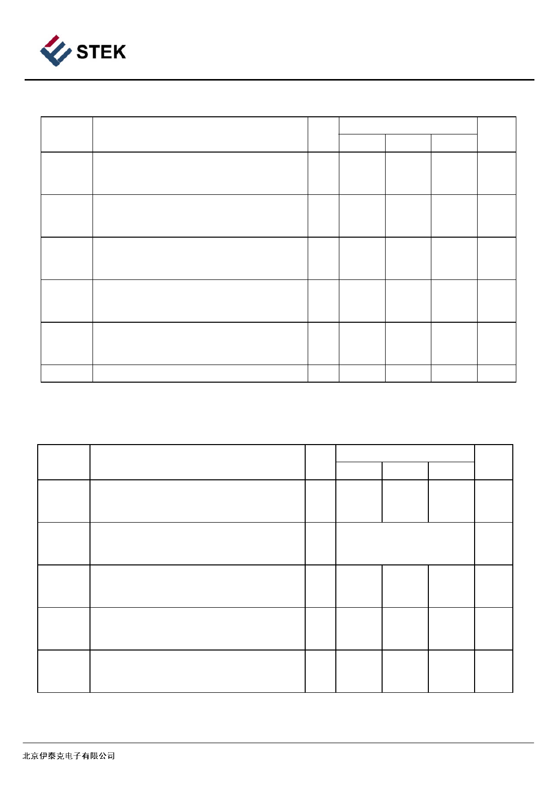
AC Electrical Characteristics
Symbol
Parameter
(CL=50pF, RL=200 k , Input t r =t f =20
ns)
VCC
Guaranteed Limit
V -55°C 25°C 125°C Unit
fmax Maximum Clock Frequency
5.0 2.5
2.5
2.0 MHz
10
5
5
4.0
15 5.5
5.5
5.0
tPLH, tPHL MaximumPropagation Delay, Clock to Decode 5.0 650
650
800
ns
Output (Figure 1)
10 270
270
350
15 170
170
250
tPLH, tPHL Maximum Propagation Delay, Clock to Carry 5.0 600
600
750
ns
Output (Figure 1)
10 250
250
300
15 160
160
200
tTLH, tTHL Maximum Output Transition Time, Carry
Output or Decode Output (Figure 1)
5.0 200
200
300
ns
10 100
100
150
15
80
80
120
tPLH, tPHL Maximum Propagation Delay, Reset to
Carry
Output or Decode Output (Figure 1)
5.0 530
530
700
ns
10 230
230
300
15 170
170
250
CIN Maximum Input Capacitance
-
5
pF
Timing
Requirements
(VCC=5.0V +- 10%, CL=50pF, RL=200 k , Input t r =t f =20
ns)
Symbol
Parameter
V ᄈ -55°C 25°C 125°C Unit
tw
Minimum Pulse Width, Clock (Figure 1)
5.0 200
200
300
ns
10
90
90
150
15
60
60
100
tr, tf Maximum Input Rise and Fall Times, Clock 5.0
(Figure 1)
10
UNLIMITED
ms
15
tw
Minimum Pulse Width, Reset (Figure 1)
5.0 260
260
400
ns
10 110
110
180
15
60
60
100
trem Minimum Removal Time, Reset (Figure 1)
5.0 400
400
550
ns
10 280
280
400
15 150
150
200
tSU Minimum Setup Time, Clock Inhibit to Clock 5.0 230
230
300
ns
(Figure 1)
10 100
100
150
15
70
70
100
BEIJING ESTEK ELECTRONICS CO.,LTD
4
Share Link: 