LA8120T データシートの表示(PDF) - SANYO -> Panasonic
部品番号
コンポーネント説明
メーカー
LA8120T Datasheet PDF : 8 Pages
| |||
LA8120T
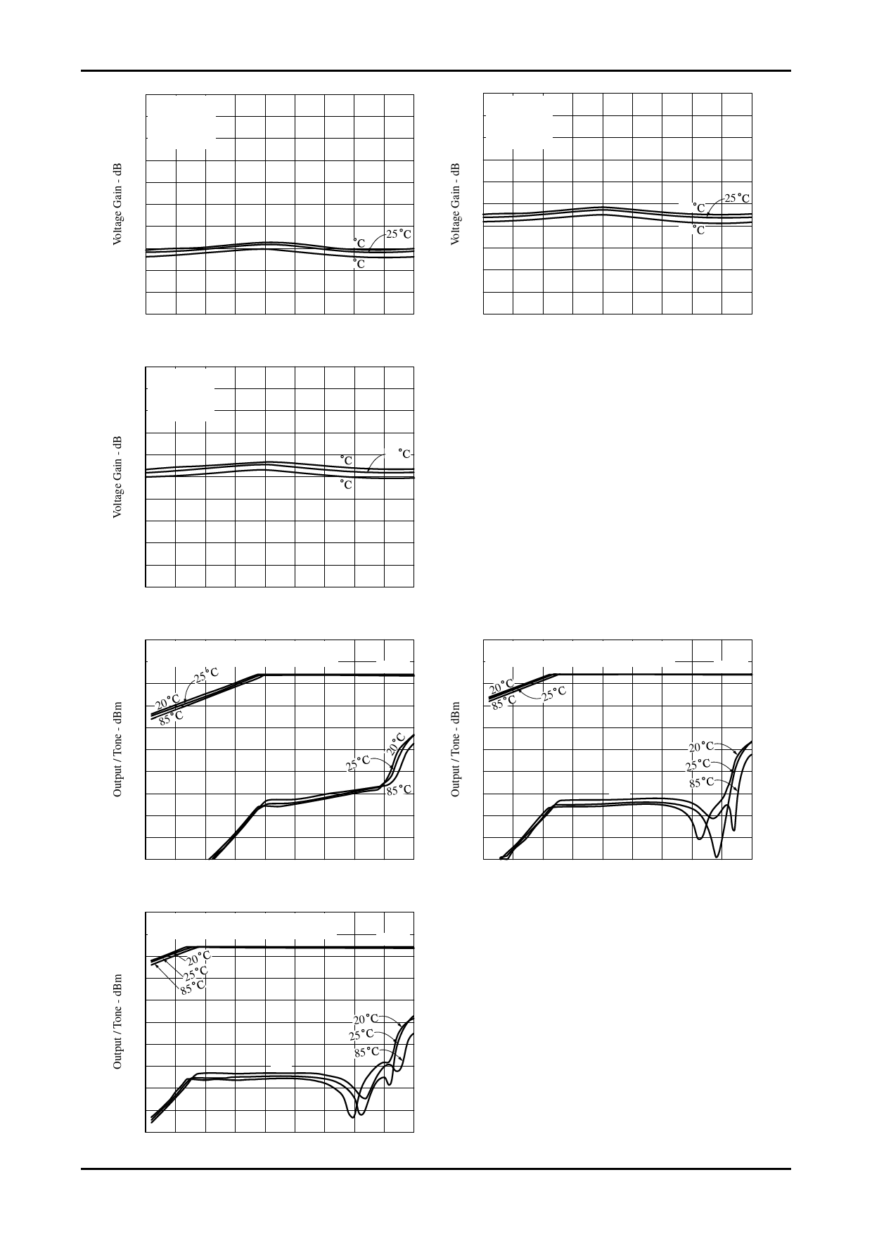
Gain - Frequency Characteristic
70
VCC = 5.0 V
65 PIN5 : OPEN
Vagc = 2.5 V
60 Circuit2
55
Gain - Frequency Characteristic
70
VCC = 5.0 V
65 PIN5 : GND
Vagc = 2.5 V
60 Circuit2
55
50
50
45
45
25
20
40
40
25
85
35
20
35
85
30
30
25
20
10 20 30 40 50 60 70 80 90 100
Frequency - MHz
Gain - Frequency Characteristic
70
VCC = 5.0 V
65 PIN5 : VCC
Vagc = 2.5 V
60 Circuit2
55
50
20
25
45
85
40
25
20
10 20 30 40 50 60 70 80 90 100
Frequency - MHz
35
30
25
20
10 20 30 40 50 60 70 80 90 100
Frequency - MHz
Intermodulation Characteristic
0 VCC = 5.0 V, PIN5 : OPEN
-10 Frequency = 44 MHz, 45 MHz, Circuit4
Output
-20
25
-30 20
-40 85
-50
-60
25
-70
IM3
85
Intermodulation Characteristic
0 VCC = 5.0 V, PIN5 : GND
-10 Frequency = 44 MHz, 45 MHz, Circuit4
Output
-20 20
-30 85
25
-40
-50
20
-60
25
85
-70
IM3
-80
-80
-90
-100
-60 -55 -50 -45 -40 -35 -30 -25 -20 -15
Input / Tone - dBm
Intermodulation Characteristic
0 VCC = 5.0 V, PIN5 : VCC
-10 Frequency = 44 MHz, 45 MHz, Circuit4
Output
-20
20
-30
25
85
-40
-50
20
25
-60
85
-70
IM3
-80
-90
-100
-60 -55 -50 -45 -40 -35 -30 -25 -20 -15
Input / Tone - dBm
The vertical axis (Output/Tone) on this graph shows
the values displayed by the spectrum analyzer for
circuit 4.
The actual output power for the corresponding pins
is given by the following formula.
{output power [dBm]}=
{displayed value [dBm]}+10 ⋅ log (250 Ω/50 Ω)
-90
-100
-60 -55 -50 -45 -40 -35 -30 -25 -20 -15
Input / Tone - dBm
No.8130-7/8
Share Link: 