LCE6.5A(2012) гғҮгғјгӮҝгӮ·гғјгғҲгҒ®иЎЁзӨәпјҲPDFпјү - Vishay Semiconductors
йғЁе“Ғз•ӘеҸ·
гӮігғігғқгғјгғҚгғігғҲиӘ¬жҳҺ
гғЎгғјгӮ«гғј
LCE6.5A Datasheet PDF : 4 Pages
| |||
www.vishay.com
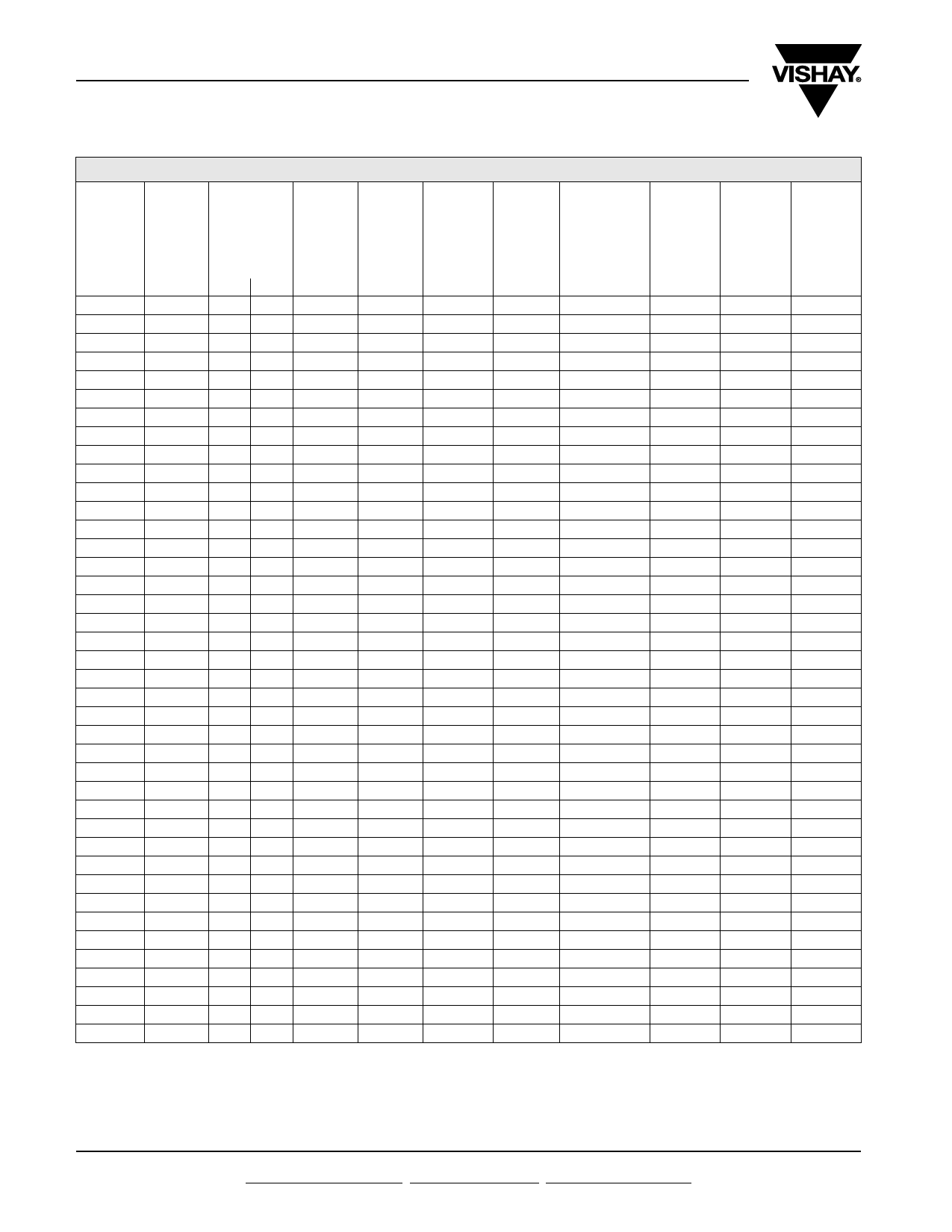
LCE6.5A thru LCE28A
Vishay General Semiconductor
ELECTRICAL CHARACTERISTICS (TA = 25 В°C unless otherwise noted)
PART
NUMBER
BREAKDOWN
VOLTAGE
VBR
(V)
MIN. MAX.
TEST
CURRENT
IT
(mA)
STAND-OFF
VOLTAGE
VWM
(V)
MAXIMUM
REVERSE
LEAKAGE
AT VWM
ID (ОјA)
MAXIMUM
PEAK
PULSE
CURRENT
(FIG.3)
IPP
(A)
MAXIMUM
CLAMPING
VOLTAGE
AT
IPP
VC (V)
MAXIMUM
JUNCTION
CAPACITANCE
AT 0 (V)
(pF)
LCE6.5A 7.22 7.98 10.0
6.5
1000
100
11.2
100
MAXIMUM
INVERSE
BLOCKING
VOLTAGE
VWIB
(V)
75
MAXIMUM
INVERSE
BLOCKING
LEAKAGE
CURRENT
AT VWIB
ID (mA)
1.0
MINIMUM
PEAK
INVERSE
BLOCKING
VOLTAGE
VPIB
(V)
100
LCE7.0A 7.78 8.6 10.0
7.0
500
100
12.0
100
75
1.0
100
LCE7.5A 8.33 9.21 10.0
7.5
250
100
12.9
100
75
1.0
100
LCE8.0A 8.89 9.83 1.0
8.0
100
100
13.6
100
75
1.0
100
LCE8.5A 9.44 10.4 1.0
8.5
50.0
100
14.4
100
75
1.0
100
LCE9.0A 10.0 11.1 1.0
9.0
10.0
97
15.4
100
75
1.0
100
LCE10A 11.1 12.3 1.0
10.0
5.0
88
17.0
100
75
1.0
100
LCE11A 12.2 13.5 1.0
11.0
5.0
82
18.2
100
75
1.0
100
LCE12A 13.3 14.7 1.0
12.0
5.0
75
19.9
100
75
1.0
100
LCE13A 14.4 15.9 1.0
13.0
5.0
70
21.5
100
75
1.0
100
LCE14A 15.6 17.2 1.0
14.0
5.0
65
23.2
100
75
1.0
100
LCE15A 16.7 18.5 1.0
15.0
5.0
61
24.4
100
75
1.0
100
LCE16A 17.8 19.7 1.0
16.0
5.0
57
26.0
100
75
1.0
100
LCE17A 18.9 20.9 1.0
17.0
5.0
54
27.6
100
75
1.0
100
LCE18A 20.0 22.1 1.0
18.0
5.0
51
29.2
100
75
1.0
100
LCE20A 22.2 24.5 1.0
20.0
5.0
46
32.4
100
75
1.0
100
LCE22A 24.4 26.9 1.0
22.0
5.0
42
35.5
100
75
1.0
100
LCE24A 26.7 29.5 1.0
24.0
5.0
39
38.9
100
75
1.0
100
LCE26A 28.9 31.9 1.0
26.0
5.0
36
42.1
100
75
1.0
100
LCE28A 31.1 34.4 1.0
28.0
5.0
33
45.5
100
75
1.0
100
Note
вҖў All the above devices are UL listed for Telecom application protection 497B, file number E136766
ORDERING INFORMATION (Example)
PREFERRED PIN UNIT WEIGHT (g) PREFERRED PACKAGE CODE
LCE6.5A-E3/54
0.968
54
BASE QUANTITY
1400
DELIVERY MODE
13" diameter paper tape and reel
RATINGS AND CHARACTERISTICS CURVES (TA = 25 В°C unless otherwise noted)
100
100
Power Dissipation
75
10
Peak Power (Single Pulse)
TJ = Initial Temperature
50
1
L = 0.375" (9.5 mm)
25 Lead Lengths
0.1
0.1 Вөs 1.0 Вөs 10 Вөs 100 Вөs 1.0 ms 10 ms
td - Pulse Width
Fig. 1 - Peak Pulse Power Rating Curve
0
0 25 50 75 100 125 150 175
TL - Lead Temperature (В°C)
Fig. 2 - Power Derating Curve
Revision: 24-Sep-12
2
Document Number: 88357
For technical questions within your region: DiodesAmericas@vishay.com, DiodesAsia@vishay.com, DiodesEurope@vishay.com
THIS DOCUMENT IS SUBJECT TO CHANGE WITHOUT NOTICE. THE PRODUCTS DESCRIBED HEREIN AND THIS DOCUMENT
ARE SUBJECT TO SPECIFIC DISCLAIMERS, SET FORTH AT www.vishay.com/doc?91000
Share Link: 