LCE6.5 „Éá„Éľ„āŅ„ā∑„Éľ„Éą„ĀģŤ°®Á§ļÔľąPDFÔľČ - Vishay Semiconductors
ťÉ®ŚďĀÁē™ŚŹ∑
„ā≥„É≥„ÉĚ„Éľ„Éć„É≥„ÉąŤ™¨śėé
„É°„Éľ„āę„Éľ
LCE6.5 Datasheet PDF : 5 Pages
| |||
LCE6.5 thru LCE28A
Vishay General Semiconductor
ORDERING INFORMATION (Example)
PREFERRED P/N UNIT WEIGHT (g) PREFERRED PACKAGE CODE
LCE6.5-E3/54
0.968
54
BASE QUANTITY
1400
DELIVERY MODE
13" diameter paper tape and reel
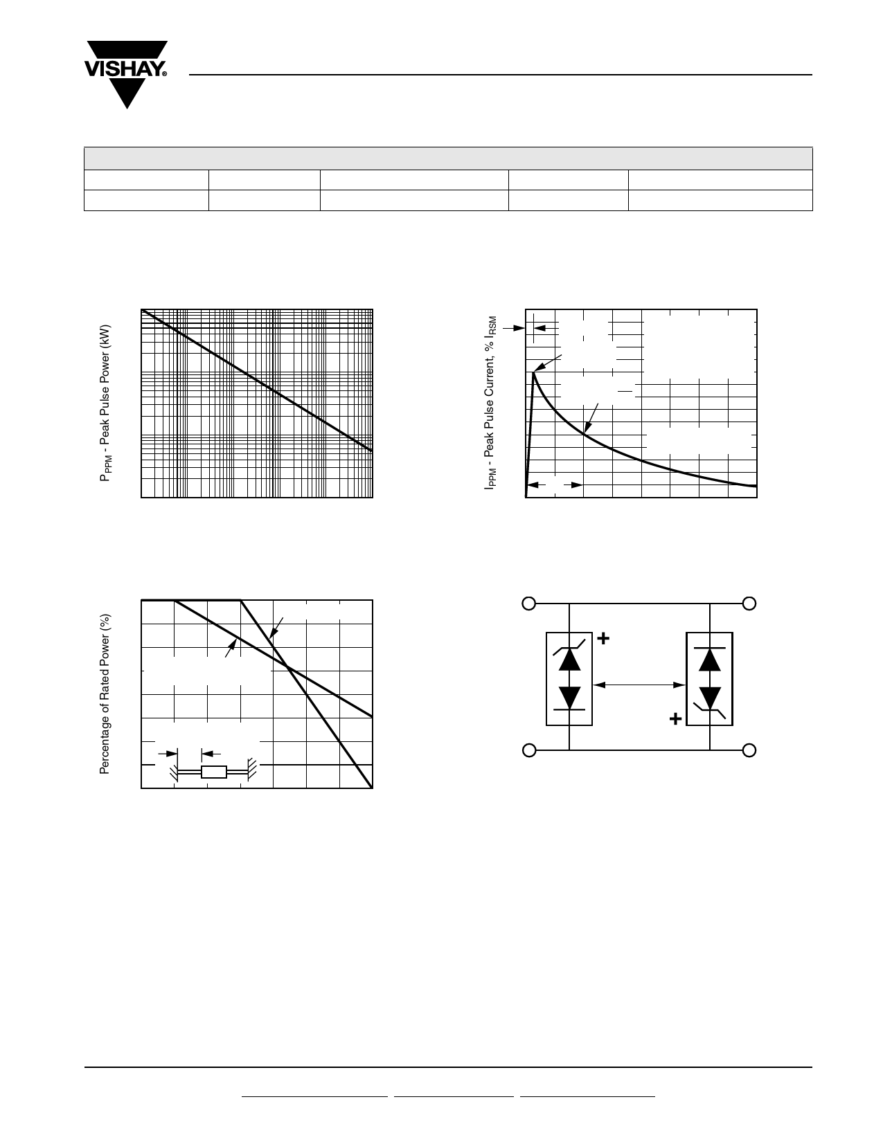
RATINGS AND CHARACTERISTICS CURVES
(TA = 25 ¬įC unless otherwise noted)
100
10
1
0.1
0.1 ¬Ķs
1.0 ¬Ķs 10 ¬Ķs 100 ¬Ķs 1.0 ms
td - Pulse Width
10 ms
Figure 1. Peak Pulse Power Rating Curve
150
tr = 10 ¬Ķs
TJ = 25 ¬įC
Pulse Width (td)
Peak Value
is defined as the Point
IPPM
where the Peak Current
100
decays to 50 % of IPPM
Half Value - IPP
IPPM
2
50
10/1000 ¬Ķs Waveform
as defined by R.E.A.
td
0
0
1.0
2.0
3.0
4.0
t - Time (ms)
Figure 3. Pulse Waveform
100
Power Dissipation
75
Peak Power (Single Pulse)
TJ = Initial Temperature
50
L = 0.375" (9.5 mm)
25 Lead Lengths
0
0 25 50 75 100 125 150 175
TL - Lead Temperature (¬įC)
Figure 2. Power Derating Curve
Low Capacitance
TVS
Application Note: Device must be used with
two units in parallel, opposite in polarity as
shown in circuit for AC signal line protection.
Figure 4. AC Line Protection Application
Document Number: 88357 For technical questions within your region, please contact one of the following:
Revision: 20-Oct-08
PDD-Americas@vishay.com, PDD-Asia@vishay.com, PDD-Europe@vishay.com
www.vishay.com
3
Share Link: 