LTC2908 データシートの表示(PDF) - Linear Technology
部品番号
コンポーネント説明
メーカー
LTC2908 Datasheet PDF : 18 Pages
| |||
LTC2908
APPLICATIONS INFORMATION
Supply Monitoring
The LTC2908 is a low power, high accuracy, six input
supply monitoring circuit with two adjustable inputs. The
reset delay is set to a nominal of 200ms with an internal
capacitor, eliminating the need for an external timing
capacitor.
All input voltages must be above predetermined thresholds
for the reset not to be invoked. The LTC2908 asserts the
reset output during power-up, power-down and brownout
conditions on any one of the voltage inputs.
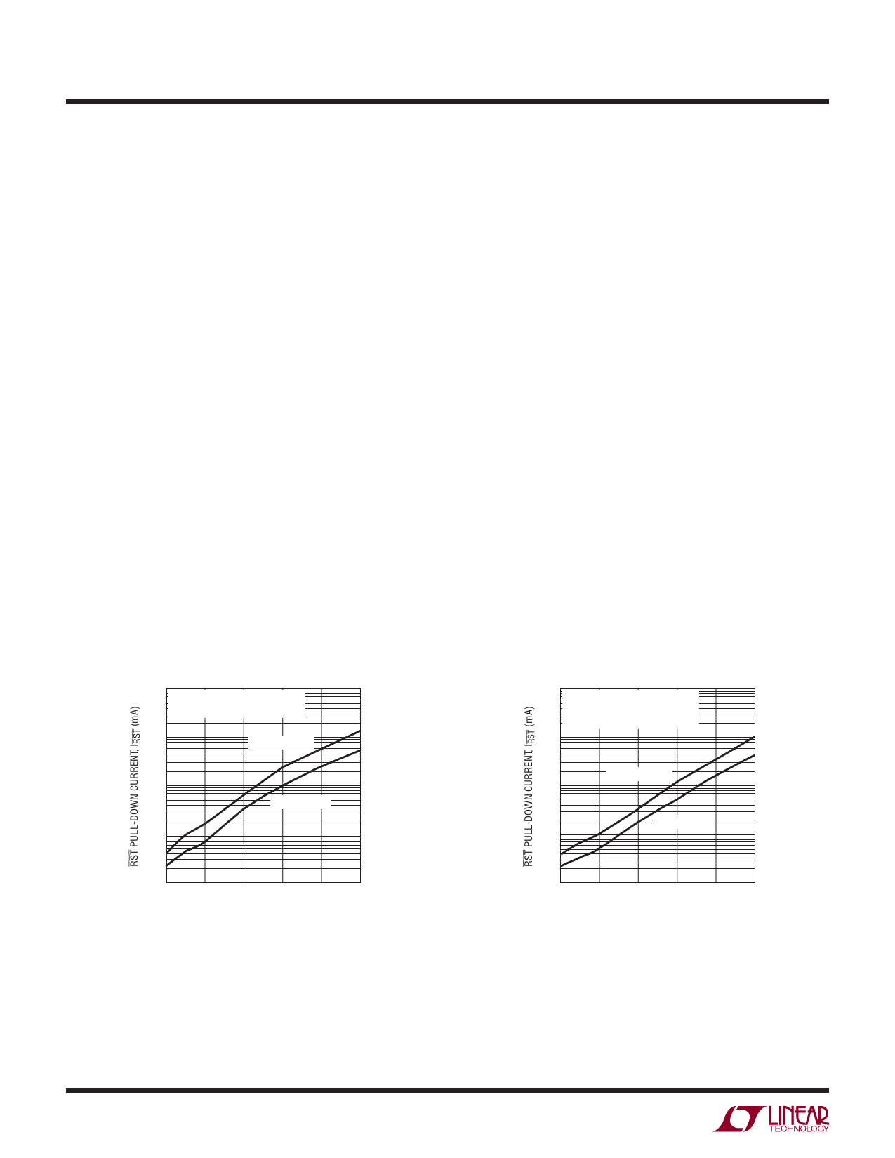
Ultralow Voltage Pull-Down on RST
The LTC2908 issues a logic low on the RST output when
any one of the inputs falls below its threshold. Ideally, the
RST logic output would remain low with the input supply
voltage down to zero volts. Most supervisors lack pull-
down capability below 1V.
The LTC2908 power supply supervisor incorporates a novel
low voltage pull-down circuit that can hold the RST line low
with as little as 200mV of input supply voltage on V1 and/or
V2 (see Figures 1 and 2). The pull-down circuit helps maintain
a low impedance path to ground, reducing the risk of the
RST node from floating to an indeterminate voltage.
Such an indeterminate voltage may trigger external logic
causing erroneous reset operation(s). Furthermore, a
mid-scale voltage level could cause external circuits
to operate in the middle of their voltage transfer
characteristic, consuming more quiescent current than
normal. These conditions could cause serious system
reliability problems.
Power-Up
During power-up, RST starts asserting low as soon as
there is at least 200mV on V1 and/or V2. The RST pull-
down capability is a function of V1 and V2 as shown in
the Typical Performance Characteristics.
The greater of V1, V2 is the internal supply voltage (VCC)
that powers the other internal circuitry. Once all the VX
inputs rise above their thresholds, an internal timer is
started. After the internal timer counts a 200ms delay
time, RST weakly pulls high to VCC.
Power-Down
On power-down, once any of the VX inputs drop below
their threshold, RST asserts logic low. VCC of at least 0.5V
guarantees a logic low of 0.15V at RST.
10
VCC = V1 = V2
V3 = V4 = VADJ1 = VADJ2 = GND
1
RST AT 150mV
0.1
RST AT 50mV
0.01
10
VCC = V1
V2 = V3 = V4 = VADJ1 = VADJ2 =
VADJ3 = VADJ4 = VADJ5 = GND
1
RST AT 150mV
0.1
RST AT 50mV
0.01
0.001
0
0.2
0.4 0.6 0.8
1
SUPPLY VOLTAGE, VCC (V)
2908 G16
Figure 1. RST Pull-Down Current vs
Supply Voltage with 2 Inputs LTC2908-A1/
LTC2908-B1
0.001
0
0.2
0.4
0.6
0.8
1
SUPPLY VOLTAGE, VCC (V)
2908 G17
Figure 2. RST Pull-Down Current vs
Supply Voltage with 1 Input
2908fd
10
Share Link: 