HDMP-1646 データシートの表示(PDF) - HP => Agilent Technologies
部品番号
コンポーネント説明
メーカー
HDMP-1646 Datasheet PDF : 15 Pages
| |||
HDMP-1636/46 (Transmitter Section)
Output Jitter Characteristics
TA = 0°C to +70°C, VCC = 3.15 V to 3.45 V
Symbol
Parameter
RJ[1]
Random Jitter at DOUT, the High Speed Electrical Data Port, specified as
1 sigma deviation of the 50% crossing point (RMS)
DJ[1] Deterministic Jitter at DOUT, the High Speed Electrical Data Port (pk-pk)
Units
ps
ps
Typ.
8
15
Note:
1. Defined by Fibre Channel Specification X3.230-1994 FC-PH Standard, Annex A, Section A.4 and tested using measurement method
shown in Figure 8.
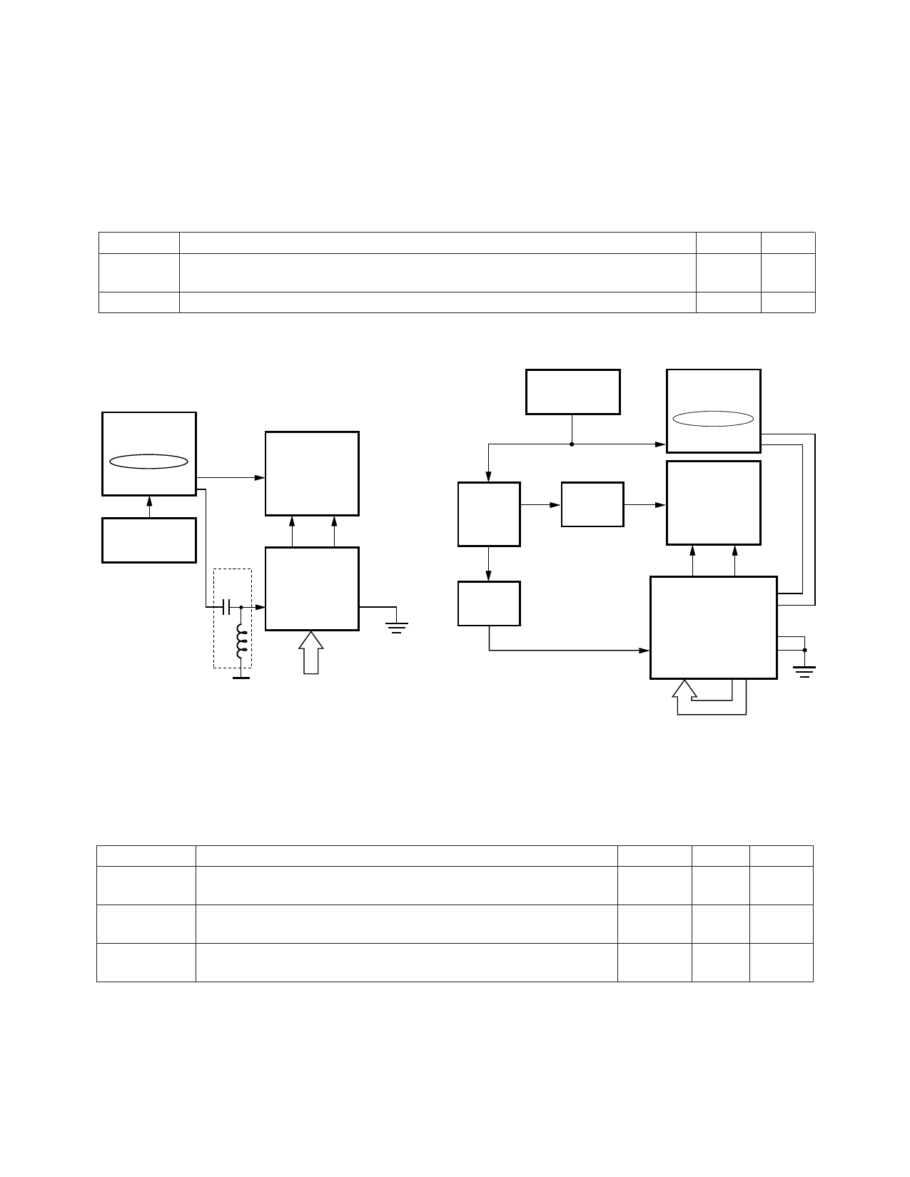
HP70841B
PATTERN
GENERATOR*
0000011111
+ DATA
- DATA
125 MHz
1.25 GHz
HP83480A
OSCILLOSCOPE
TRIGGER
CH1 CH2
HP70311A
CLOCK SOURCE
* PATTERN
GENERATOR
PROVIDES A
DIVIDE BY
10 FUNCTION.
BIAS
TEE
+DOUT -DOUT
HDMP-1636
REFCLK LOOPEN
Tx[0..9]
1.4 V
0011111000
(STATIC K28.7)
HP70311A
CLOCK SOURCE
DIVIDE
BY 10
CIRCUIT
(DUAL
OUTPUT)
1.25 GHz
DIVIDE
BY 2
CIRCUIT
HP70841B
PATTERN
GENERATOR
+K28.5, -K28.5
+ DATA
- DATA
HP83480A
OSCILLOSCOPE
TRIGGER
CH1 CH2
VARIABLE
DELAY
TTL
125 MHz
+DOUT -DOUT
-DIN
+DIN
HDMP-1636
REFCLK
ENBYTSYNC
LOOPEN
Tx[0..9] Rx[0..9]
a. Block Diagram of RJ Measurement Method.
b. Block Diagram of DJ Measurement Method.
Figure 8. Transmitter Jitter Measurement Method.
HDMP-1636/46 (TRx)
Thermal and Power Temperature Characteristics
TA = 0°C to +70°C, VCC = 3.15 V to 3.45 V
Symbol
Parameter
PD,TRx[1,2]
Transceiver Power Dissipation, Outputs Open, Parallel Data
has 5 Ones and 5 Zeroes
PD,TRx[1,2,3] Transceiver Power Dissipation, Outputs Connected per
Recommended Bias Terminations with Idle Pattern
Θjc[4]
Thermal Resistance, Junction to Case HDMP-1636
HDMP-1646
Units
mW
Typ.
630
mW
685
°C/Watt 10
7
Max.
850
900
Notes:
1. PD is obtained by multiplying the max VCC by the max ICC and subtracting the power dissipated outside the chip at the high speed
bias resistors.
2. Typical value specified with VCC = 3.3 volts, maximum value specified with VCC = 3.45 volts.
3. Specified with high speed outputs biased with 150 Ω resistors and receiver TTL outputs driving 10 pF loads.
4. Based on independent package testing by HP. Θja for these devices is 48°C/Watt for the HDMP-1636 and 44°C/Watt for the
HDMP-1646. Θja is measured on a standard 3x3" FR4 PCB in a still air environment. To determine the actual junction temperature
in a given application, use the value as described as follows: Tj = TC + (Θjc x Pd), where TC is the case temperature measured on
the top center of the package and PD is the power being dissipated.
719
Share Link: 