MSR860 データシートの表示(PDF) - ON Semiconductor
部品番号
コンポーネント説明
メーカー
MSR860 Datasheet PDF : 6 Pages
| |||
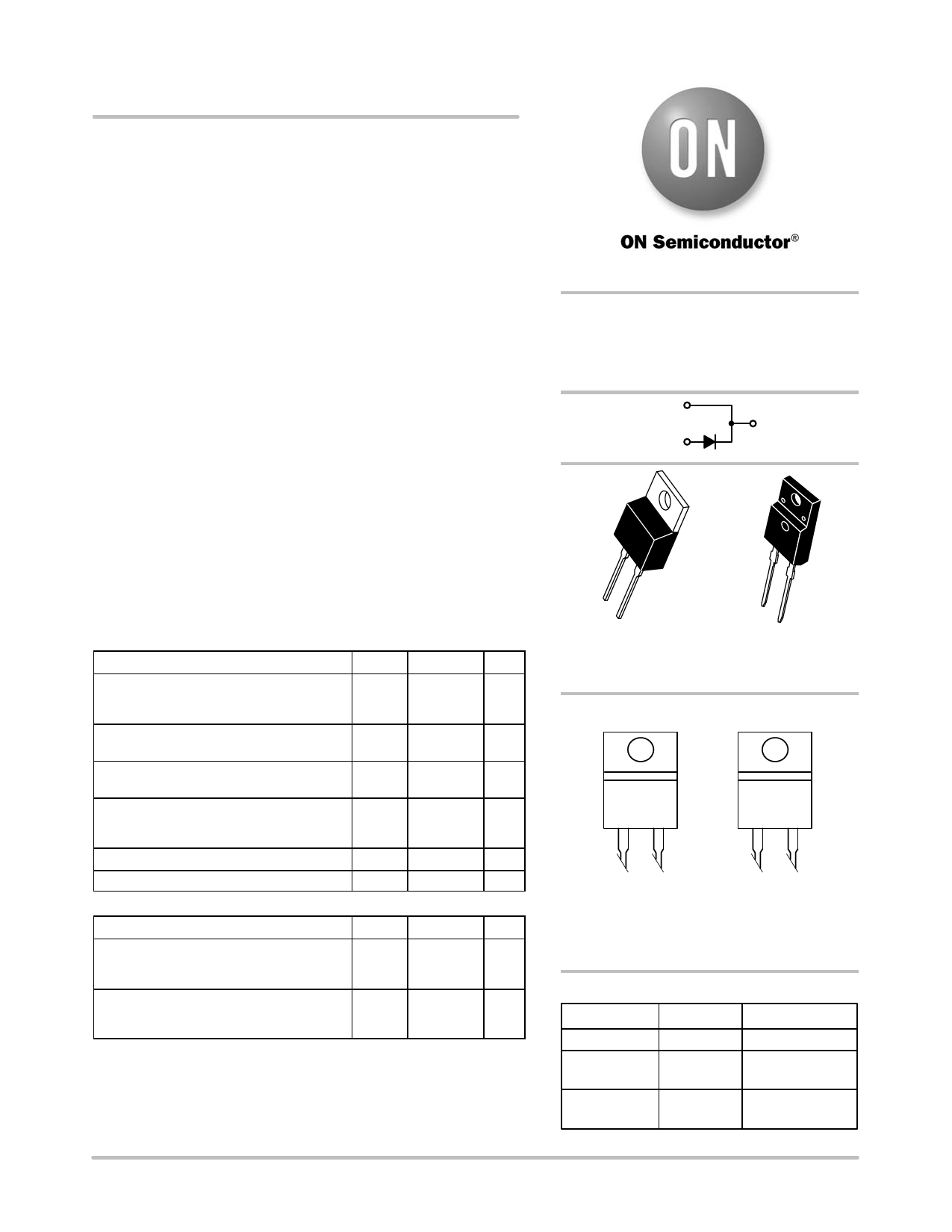
MSR860, MSRF860
SWITCHMODEt Soft
Recovery Power Rectifiers
Plastic TO−220 Package
These state−of−the−art devices are designed for use as free wheeling
diodes in variable speed motor control applications and switching
power supplies.
Features
• Soft Recovery with Guaranteed Low Reverse Recovery Charge
(QRR) and Peak Reverse Recovery Current (IRRM)
• 150°C Operating Junction Temperature
• Epoxy meets UL 94 V−0 @ 0.125 in
• Low Forward Voltage
• Low Leakage Current
• Pb−Free Package is Available
Mechanical Characteristics:
• Case: Epoxy, Molded
• Weight: 1.9 Grams (Approximately)
• Finish: All External Surfaces Corrosion Resistant and Terminal
Leads Readily Solderable
• Lead Temperature for Soldering Purposes:
260°C Max. for 10 Seconds
MAXIMUM RATINGS
Rating
Peak Repetitive Reverse Voltage
Working Peak Reverse Voltage
DC Blocking Voltage
Average Rectified Forward Current
(Rated VR, TC = 125°C)
Peak Repetitive Forward Current (Rated
VR, Square Wave, 20 kHz, TC = 125°C)
Non−Repetitive Peak Surge Current
(Surge Applied at Rated Load Conditions
Halfwave, Single Phase, 60 Hz)
Storage/Operating Case Temperature
Operating Junction Temperature
THERMAL CHARACTERISTICS
Symbol Value Unit
VRRM
600
V
VRWM
VR
IO
8.0
A
IFRM
16
A
IFSM
100
A
Tstg, TC −65 to +150 °C
TJ −65 to +150 °C
Parameter
Symbol Value Unit
MSR860
Thermal Resistance, Junction−to−Case
Thermal Resistance, Junction−to−Ambient
RqJC
RqJA
°C/W
1.6
72.8
MSRF860
Thermal Resistance, Junction−to−Case
Thermal Resistance, Junction−to−Ambient
RqJC
RqJA
°C/W
4.75
75
Stresses exceeding Maximum Ratings may damage the device. Maximum
Ratings are stress ratings only. Functional operation above the Recommended
Operating Conditions is not implied. Extended exposure to stresses above the
Recommended Operating Conditions may affect device reliability.
http://onsemi.com
SOFT RECOVERY
POWER RECTIFIER
8.0 AMPERES, 600 VOLTS
1
4
3
4
4
1
3
TO−220AC
CASE 221B
STYLE 1
1
3
TO−220 FULLPAK
CASE 221E
STYLE 1
MARKING DIAGRAMS
AY WWG
MSR860
KA
AY WWG
MSRF860
KA
A
= Assembly Location
Y
= Year
WW = Work Week
G
= Pb−Free Package
KA = Diode Polarity
ORDERING INFORMATION
Device
MSR860
MSR860G
MSRF860G
Package
TO−220AC
TO−220AC
(Pb−Free)
TO−220FP
(Pb−Free)
Shipping
50 Units/Rail
50 Units/Rail
50 Units/Rail
© Semiconductor Components Industries, LLC, 2008
1
June, 2008 − Rev. 5
Publication Order Number:
MSR860/D
Share Link: 