NE5537 データシートの表示(PDF) - Philips Electronics
部品番号
コンポーネント説明
メーカー
NE5537 Datasheet PDF : 8 Pages
| |||
Philips Semiconductors Linear Products
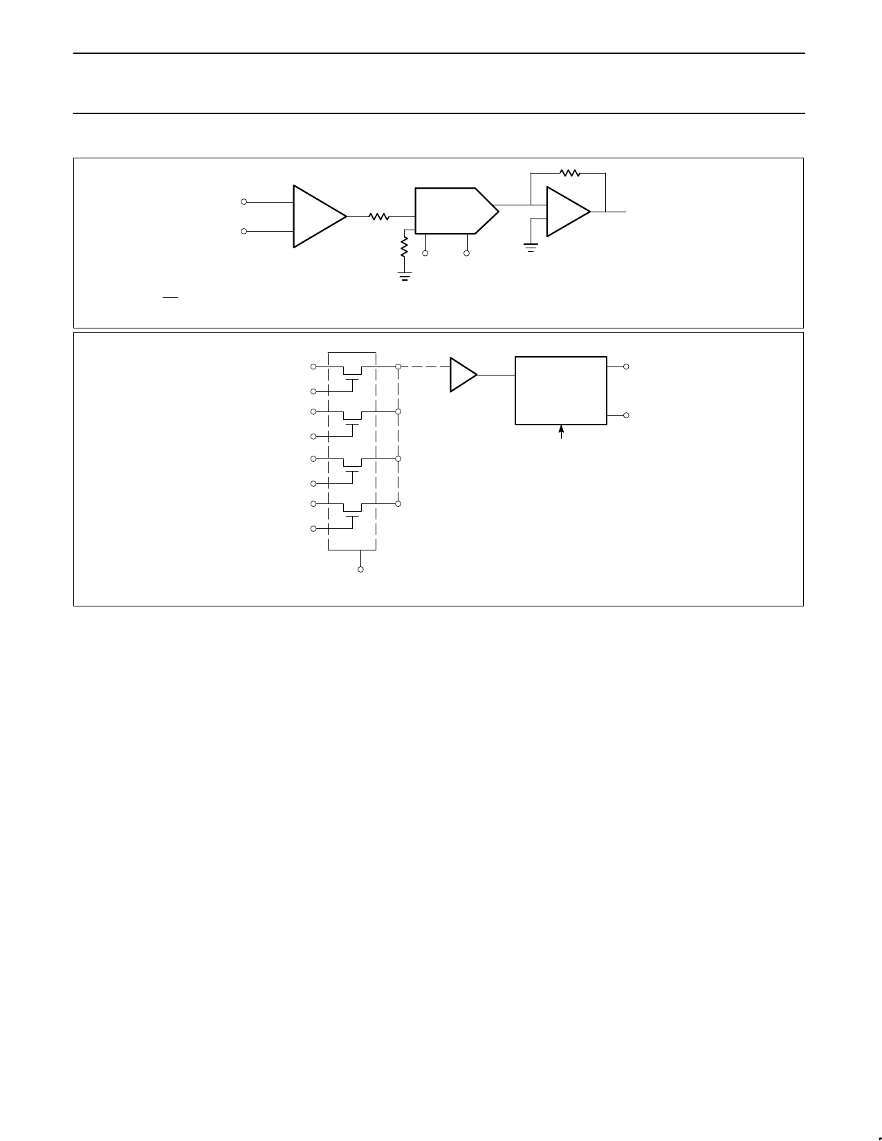
Sample-and-hold amplifier
Product specification
NE/SE5537
5k
VIN
NE5537
5k
5008/DAC-08
+VREFIN
D0-D7
530
VOUT
NOTE:
VOUT
1
+ VIN x 256
(20 D0 ) 21D1 ) 27D7) Equation 1
Figure 2. Multiplying DAC Application
ANALOG INPUT 1
CONTROL 1
ANALOG INPUT 2
CONTROL 2
ANALOG INPUT 3
CONTROL 3
ANALOG INPUT 4
CONTROL 4
SD5000
NE5537
D0
A/D
CONVERTER
D7
SUCCESSIVE APPROXIMATION
(NE5034, NE5037)
or INTEGRATING TYPE ADC
SUBSTRATE
Figure 3. Analog Data Multiplexing
A curve labeled “Aperture Time” has been included for sampling
conditions where the input is steady during the sampling period, but
may experience a sudden change nearly coincident with the “HOLD”
command. This curve is based on a 1mV error fed into the output.
SPECIAL NOTES
1. Not all definitions herein defined are measured parametrically for
the NE5537, but are legitimate terms used in sample-and-hold
systems.
A second curve, “Hold Settling Time,” indicates the time required for
the output to settle to 1mV after the “HOLD” command.
Digital Feedthrough
Fast rise time logic signals can cause hold errors by feeding
externally into the analog input at the same time the amplifier is put
into the hold mode. To minimize this problem, board layout should
keep logic lines as far as possible from the analog input. Grounded
guarding traces may also be used around the input line, especially if
it is driven from a high impedance source. Reducing high amplitude
logic signals to 2.5V will also help.
2. Reference should be made to Design Engineering, Volumes 23
(Nov. 8, 1978), 25 (Dec. 6, 1978) and 26 (Dec. 20, 1978) for
articles written by Eugene Zuch of Datel Systems, Inc., for a
further discussion of sample-and-hold circuits.
3. Reference also made to National Semiconductor Corporation’s
Special Functions Data Book (1976).
Logic signals also couple to the hold capacitor. This hold capacitor
should be guarded by a PC card trace connected to the
sample-and-hold output. This will also minimize board leakage.
August 31, 1994
891
Share Link: 