SMCJ54 データシートの表示(PDF) - First Components International
部品番号
コンポーネント説明
メーカー
SMCJ54 Datasheet PDF : 4 Pages
| |||
Data Sheet
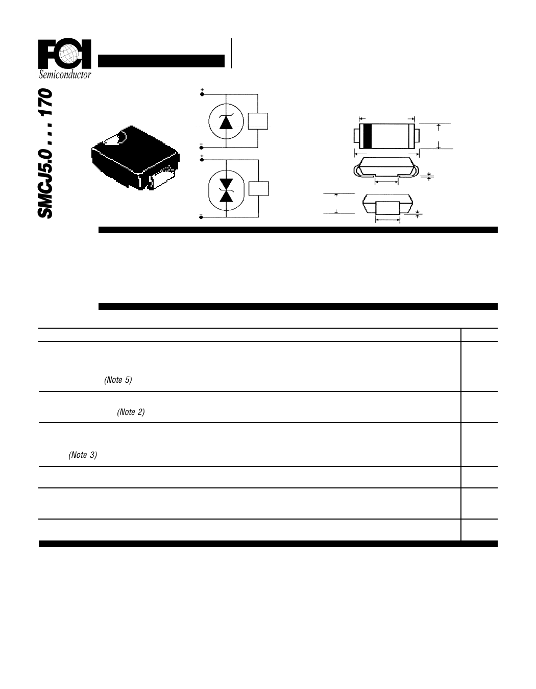
5.0V to 170V SMD TRANSIENT
VOLTAGE SUPPRESSORS
Description
TVS
Device
Load
Uni-Polar
TVS
Device
Load
Uni-Polar
Mechanical Dimensions
Package
SMC
6.60/7.11
7.75/8.12
5.59/6.10
.15/.30
1.91/2.41
.171
.051/.152
Features
n 1500 WATT PEAK POWER PROTECTION
n EXCELLENT CLAMPING CAPABILITY
n FAST RESPONSE TIME
n TYPICAL IR < 1µA ABOVE 10V
n GLASSPASSIVATEDCHIPCONSTRUCTION
n MEETS UL SPECIFICATION 94V-0
Electrical Characteristics @ 25OC.
SMCJ5.0...170
Units
Maximum Ratings
Peak Power Dissipation...PPK
TP = 1mS (Note 5)
......................................... 1500 Min. .......................................... Watts
Steady State Power Dissipation...PD
@ TT = 75°C (Note 2)
............................................. 5 ............................................... Watts
Non-Repetitive Peak Forward Surge Current...IFSM
............................................. 100 ............................................... Amps
@ Rated Load Conditions, 8.3 mS, ½ Sine Wave, Single Phase
(Note 3)
Weight...GRM
Soldering Requirements (Time & Temp)...ST
@ 250°C
............................................. 0.20 ............................................... Grams
............................................. 11 Sec. ........................................... Min. to
Solder
Operating & Storage Temperature Range...TJ, TSTRG ......................................... -65 to 175 .......................................... °C
NOTES: 1. For Bi-Directional Applications, Use C or CA. Electrical Characteristics Apply in Both Directions.
2. Mounted on 8mm Copper Pads to Each Terminal.
3. 8.3 mS, ½ Sine Wave, Single Phase Duty Cycle, @ 4 Pulses Per Minute Maximum.
4. VBR Measured After It Applies for 300 uS. IT = Square Wave Pulse or Equivalent.
5. Non-Repetitive Current Pulse. Per Fig. 3 and Derated Above TA = 25°C per Fig. 2.
Page 10-44
Share Link: 