HV3922 データシートの表示(PDF) - Supertex Inc
部品番号
コンポーネント説明
メーカー
HV3922 Datasheet PDF : 5 Pages
| |||
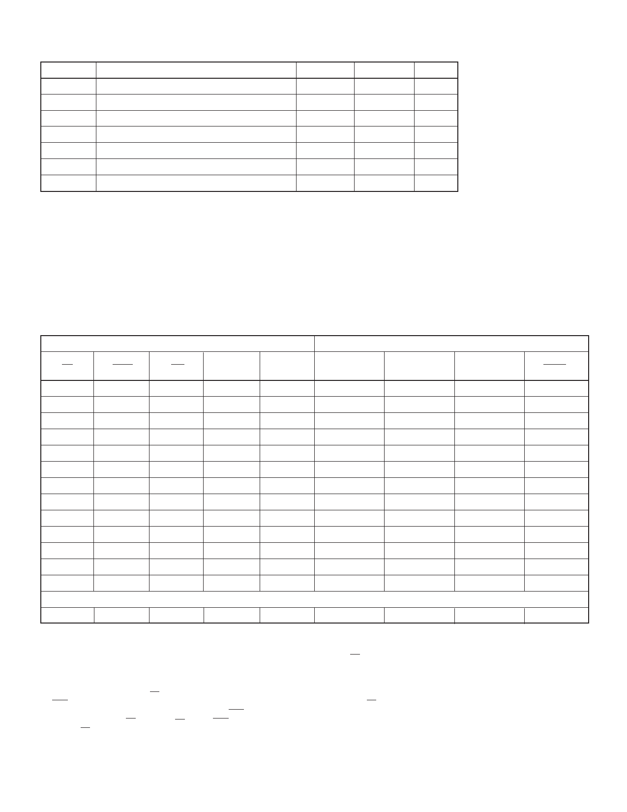
Recommended Operating Conditions
Symbol
VCC
VIN
VLL
VPP
IPD(N)H
TA
CL
Parameter
Logic Supply Voltage
DC Logic Input Voltage
VLL Supply Voltage
VPP Supply Voltage
High-State Continuous PD(N) Source Current
Ambient Operating Temp
DRV(N) Load Capacitance
Min
Max
4.5
5.5
0
VCC
-3.5
-2.5
200
220
1.7
-55
+125
0
0.006
Notes:
1.VPP rise time (dv/dt) should be less than 50V/µS.
2.Power-up sequence should be the following:
A) Connect ground;
B) Apply V ;
PP
C) Apply VCC;
D) Apply VLL;
E) Set all inputs to a known state. Power-down sequence should be the reverse of the above.
Units
V
V
V
V
mA
°C
µF
HV3922
Function Table
Input
CS
ENA
OE
H
X
H
X
H
H
L
L
H
L
L
H
L
L
H>L
L
L
H>L
H
X
H>L
X
H
H>L
X
X
H
(At Power Up)
X
X
VIH
Data
D(N)
X
X
H
L
H
L
X
X
X
X
VTH
Level2
Pass
Pass
Pass
Pass
P/F
P/F
P/F
P/F
Pass
Pass
Fail
Internal
Latch Q(N)
Previous State
Output
PD(N)
DRV(N)
Previous State Previous State
Previous State Previous State Previous State
Set
Previous State Previous State
Reset
Previous State Previous State
Set
VDH
VDL
Reset
HI-Z
VDH
Previous State
Set
VDH
VDL
Reset
HI-Z
VDH
Previous State
Set
VDH
VDL
Reset
HI-Z
VDH
—
HI-Z
VDL
Fault
VFH
VFH
VFH
VFH
VFH
VFH
VFH
VFH
VFH
VFH
VFL
P/F
Set
VDH
VDL
VFH
Notes:
1. X indicates “Don’t Care” input state (L or H).
2. The output threshold is internally tested for each PD(N) output; the pass condition occurs when OE = H and:
A) PD(N) driving high with output > VTH (MAX), or may occurs if PD(N) driving high and output > VTH (MIN) and < VTL (MAX).
OR
B) PD(N) driving Low with output < VTH (MIN), or may occur if PD(N) driving low and output < VTH (MAX) and < VTL (MIN).
The fail condition occurs when OE = H and conditions for “pass” are not satisfied.
3. Fault output = VFL indicates a fault has been detected in at least one of the PD(N) output loads when OE = H. All other outputs shall function normally when a fault
condition has been detected for one of the outputs. The Fault output shall remain in the low state, regardless of the state of the output which initiated the fault status, until
the next falling edge of OE. Whenever OE = L, the Fault output is forced to VFH, and the fault latch is reset. If the fault condition persists, the fault response repeats each
time the OE input is set to H.
4. H>L indicates falling edge (H to L).
5. HI-Z indicates no current is sourced to output PD(N).
6. P/F indicates “Pass” or “Fail” fault threshold conditions.
12-20
Share Link: 