STK4132 データシートの表示(PDF) - SANYO -> Panasonic
部品番号
コンポーネント説明
メーカー
STK4132 Datasheet PDF : 7 Pages
| |||
STK41322
Operating Characteristics at Ta = 25˚C, VCC=±23V, RL=8Ω (non-inductive load), Rg=600Ω, VG=40dB
Parameter
Symbol
Conditions
Ratings
Unit
min
typ
max
Quiescent current
Output power
ICCO
PO1
PO2
VCC=±28V
THD=0.4%, f=20Hz to 20kHz
VCC=±20V, THD=1.0%, RL=4Ω,
f=1kHz
20
40
100 mA
20
W
20
W
Total harmonic distortion
Frequency response
Input resistance
Neutral voltage
Output noise voltage
Muting voltage
THD
fL, fH
ri
VN
VNO
VM
PO=1.0W, f=1kHz
PO=1.0W,
+0
–3
dB
PO=1.0W, f=1kHz
VCC=±50.5V
VCC=±28V, Rg=10kΩ
20 to 50k
55
–70
0
–2
–5
0.3 %
Hz
kΩ
+70 mV
1.2 mVrms
–10 V
Note.
All tests are made using a constant-voltage supply unless otherwise specified.
Available time for load short-circuit and output noise voltage are measured using the transformer supply specified below.
The output noise voltage is the peak value of an average-reading meter with an rms value scale (VTVM). A regulated AC
supply (50Hz) should be used to eliminate the effects of AC primary line flicker noise.
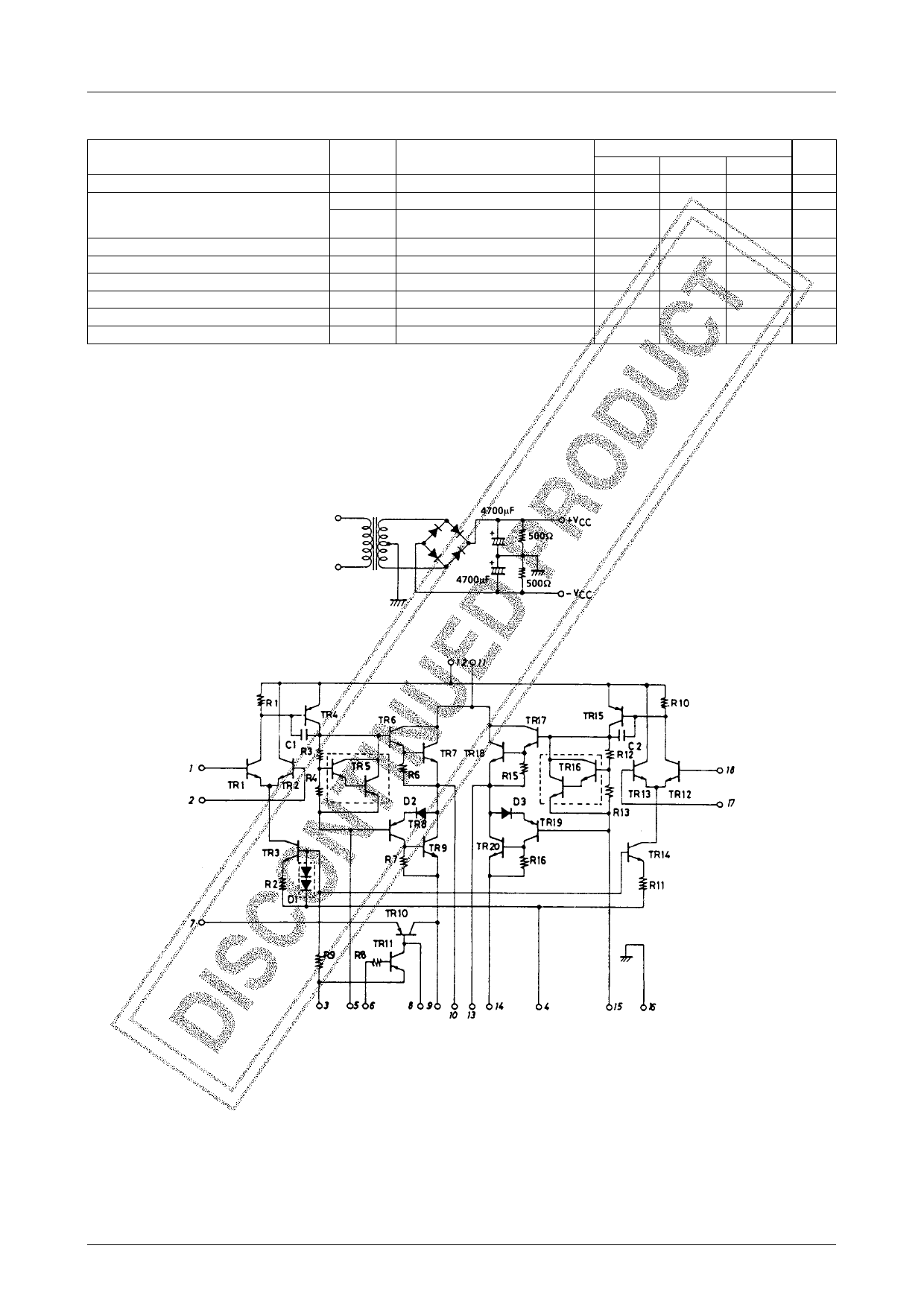
Specified Transformer Supply (RP-25 or Equivalent)
Equivalent Circuit
No.2668–2/8
Share Link: 