KU376 データシートの表示(PDF) - Intel
部品番号
コンポーネント説明
メーカー
KU376 Datasheet PDF : 95 Pages
| |||
376 EMBEDDED PROCESSOR
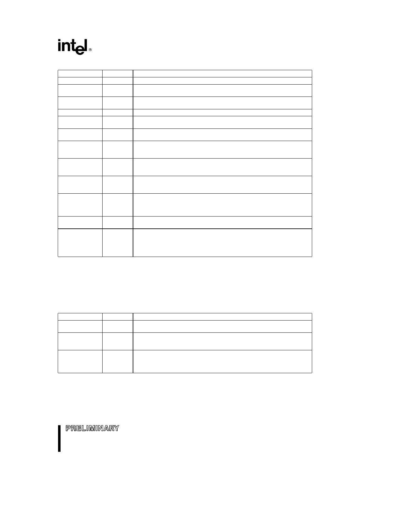
Bit Position
0
2
4
6
7
8
9
10
11
12 13
14
16
Name
CF
PF
AF
ZF
SF
TF
IF
DF
OF
IOPL
NT
RF
Table 2 1 Flag Definitions
Function
Carry Flag Set on high-order bit carry or borrow cleared otherwise
Parity Flag Set if low-order 8 bits of result contain an even number
of 1-bits cleared otherwise
Auxiliary Carry Flag Set on carry from or borrow to the low order
four bits of AL cleared otherwise
Zero Flag Set if result is zero cleared otherwise
Sign Flag Set equal to high-order bit of result (0 if positive 1 if
negative)
Single Step Flag Once set a single step interrupt occurs after the
next instruction executes TF is cleared by the single step interrupt
Interrupt-Enable Flag When set external interrupts signaled on the
INTR pin will cause the CPU to transfer control to an interrupt vector
specified location
Direction Flag Causes string instructions to auto-increment (default)
the appropriate index registers when cleared Setting DF causes auto-
decrement
Overflow Flag Set if the operation resulted in a carry borrow into
the sign bit (high-order bit) of the result but did not result in a
carry borrow out of the high-order bit or vice-versa
I O Privilege Level Indicates the maximum CPL permitted to
execute I O instructions without generating an exception 13 fault or
consulting the I O permission bit map It also indicates the maximum
CPL value allowing alteration of the IF bit
Nested Task Indicates that the execution of the current task is
nested within another task (see Task Switching)
Resume Flag Used in conjunction with debug register breakpoints It
is checked at instruction boundaries before breakpoint processing If
set any debug fault is ignored on the next instruction It is reset at the
successful completion of any instruction except IRET POPF and
those instructions causing task switches
CONTROL REGISTER
The 80376 has a 32-bit control register called CR0 that is used to control coprocessor emulation This register
is shown in Figures 2 1 and 2 2 The defined CR0 bits are described in Table 2 2 Bits 0 4 and 31 of CR0 have
fixed values in the 80376 These values cannot be changed Programs that load CR0 should always load bits
0 4 and 31 with values previously there to be compatible with the 80386
Bit Position
1
2
3
Name
MP
EM
TS
Table 2 2 CR0 Definitions
Function
Monitor Coprocessor Extension Allows WAIT instructions to cause
a processor extension not present exception (number 7)
Emulate Processor Extension When set this bit causes a
processor extension not present exception (number 7) on ESC
instructions to allow processor extension emulation
Task Switched When set this bit indicates the next instruction using
a processor extension will cause exception 7 allowing software to test
whether the current processor extension context belongs to the
current task (see Task Switching)
9
Share Link: 