M80C286 データシートの表示(PDF) - Intel
部品番号
コンポーネント説明
メーカー
M80C286 Datasheet PDF : 60 Pages
| |||
M80C286
FUNCTIONAL DESCRIPTION
Introduction
The M80C286 is an advanced high-performance mi-
croprocessor with specially optimized capabilities for
multiple user and multi-tasking systems Depending
on the application a 10 MHz M80C286’s perform-
ance is up to eight times faster than the standard 5
MHz M8086’s while providing complete upward
software compatibility with Intel’s M8086 88 and
186 family of CPU’s
The M80C286 operates in two modes M8086 real
address mode and protected virtual address mode
Both modes execute a superset of the M8086 and
88 instruction set
In M8086 real address mode programs use real ad-
dresses with up to one megabyte of address space
Programs use virtual addresses in protected virtual
address mode also called protected mode In pro-
tected mode the M80C286 CPU automatically maps
1 gigabyte of virtual addresses per task into a 16
megabyte real address space This mode also pro-
vides memory protection to isolate the operating
system and ensure privacy of each tasks’ programs
and data Both modes provide the same base in-
struction set registers and addressing modes
The following Functional Description describes first
the base M80C286 architecture common to both
modes second M8086 real address mode and
third protected mode
M80C286 BASE ARCHITECTURE
The M8086 88 186 and 286 CPU family all contain
the same basic set of registers instructions and
addressing modes The M80C286 processor is up-
ward compatible with the M8086 M8088 and 80186
CPU’s and fully compatible with the HMOS M80286
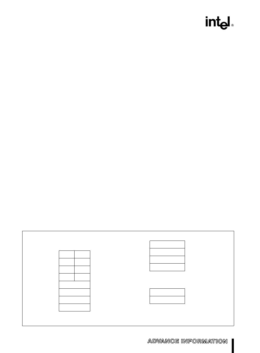
Register Set
The M80C286 base architecture has fifteen registers
as shown in Figure 2 These registers are grouped
into the following four categories
General Registers Eight 16-bit general purpose
registers used to contain arithmetic and logical oper-
ands Four of these (AX BX CX and DX) can be
used either in their entirety as 16-bit words or split
into pairs of separate 8-bit registers
Segment Registers Four 16-bit special purpose
registers select at any given time the segments of
memory that are immediately addressable for code
stack and data (For usage refer to Memory Organi-
zation )
Base and Index Registers Four of the general pur-
pose registers may also be used to determine offset
addresses of operands in memory These registers
may contain base addresses or indexes to particular
locations within a segment The addressing mode
determines the specific registers used for operand
address calculations
Status and Control Registers The 3 16-bit special
purpose registers in Figure 3 record or control cer-
tain aspects of the M80C286 processor state includ-
ing the Instruction Pointer which contains the offset
address of the next sequential instruction to be exe-
cuted
16-BIT
REGISTER
NAME
7
07
0
SPECIAL
REGISTER
FUNCTIONS
BYTE
ADDRESSABLE
(8-BIT
REGISTER
NAMES
SHOWN)
AX
AH
DX
DH
CX
CH
% BX
BH
BP
AL
MULTIPLY DIVIDE
I O INSTRUCTIONS
* DL
CL
( LOOP SHIFT REPEAT COUNT
BL
BASE REGISTERS
*
SI
DI
SP
15
GENERAL
REGISTERS
INDEX REGISTERS
*
( STACK POINTER
0
15
0
CS
DS
SS
ES
SEGMENT REGISTERS
15
0
F
IP
STATUS AND CONTROL
REGISTERS
Figure 2 Register Set
CODE SEGMENT SELECTOR
DATA SEGMENT SELECTOR
STACK SEGMENT SELECTOR
EXTRA SEGMENT SELECTOR
STATUS WORD
INSTRUCTION POINTER
2
Share Link: 