M80C286 データシートの表示(PDF) - Intel
部品番号
コンポーネント説明
メーカー
M80C286 Datasheet PDF : 60 Pages
| |||
M80C286
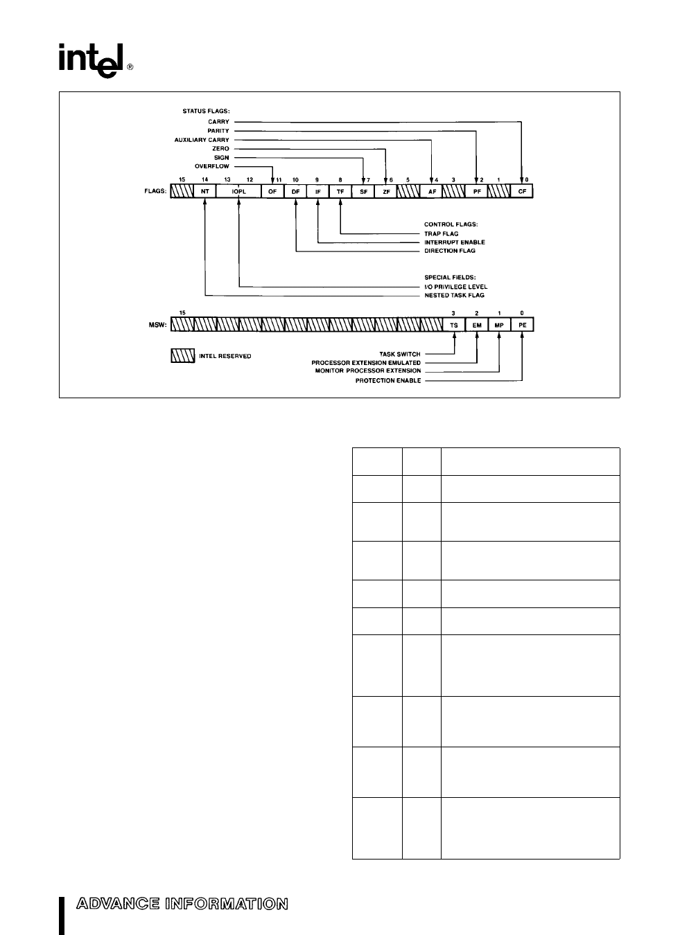
Figure 3 Status and Control Register Bit Functions
271103 – 2
Flags Word Description
The Flags word (Flags) records specific characteris-
tics of the result of logical and arithmetic instructions
(bits 0 2 4 6 7 and 11) and controls the operation
of the M80C286 within a given operating mode (bits
8 and 9) Flags is a 16-bit register The function of
the flag bits is given in Table 1
Instruction Set
The instruction set is divided into seven categories
data transfer arithmetic shift rotate logical string
manipulation control transfer high level instruc-
tions and processor control These categories are
summarized in Table 2
An M80C286 instruction can reference zero one or
two operands where an operand resides in a regis-
ter in the instruction itself or in memory Zero-oper-
and instructions (e g NOP and HLT) are usually one
byte long One-operand instructions (e g INC and
DEC) are usually two bytes long but some are en-
coded in only one byte One-operand instructions
may reference a register or memory location Two-
operand instructions permit the following six types of
instruction operations
Register to Register
Memory to Register
Immediate to Register
Memory to Memory
Register to Memory
Immediate to Memory
Table 1 Flags Word Bit Functions
Bit
Position
0
2
4
6
7
11
8
9
10
Name
CF
PF
AF
ZF
SF
OF
TF
IF
DF
Function
Carry Flag Set on high-order bit
carry or borrow cleared otherwise
Parity Flag Set if low-order 8 bits
of result contain an even number of
1-bits cleared otherwise
Set on carry from or borrow to the
low order four bits of AL cleared
otherwise
Zero Flag Set if result is zero
cleared otherwise
Sign Flag Set equal to high-order
bit of result (0 if positive 1 if negative)
Overflow Flag Set if result is a too-
large positive number or a too-small
negative number (excluding sign-bit)
to fit in destination operand cleared
otherwise
Single Step Flag Once set a sin-
gle step interrupt occurs after the
next instruction executes TF is
cleared by the single step interrupt
Interrupt-enable Flag When set
maskable interrupts will cause the
CPU to transfer control to an inter-
rupt vector specified location
Direction Flag Causes string
instructions to auto decrement
the appropriate index registers
when set Clearing DF causes
auto increment
3
Share Link: 