WPN20R12S05C データシートの表示(PDF) - Murata Manufacturing
部品番号
コンポーネント説明
メーカー
WPN20R12S05C Datasheet PDF : 4 Pages
| |||
WPN20
20W Regulated DC/DC Converter
ISOLATION CHARACTERISTICS
Parameter
Rated voltage
Test voltage
Resistance
Capacitance
Conditions
60Hz, 10 seconds
TEMPERATURE CHARACTERISTICS
Parameter
Specification
Operation
Storage
Thermal shutdown
Conditions
Case
Case
Case
RoHS COMPLIANCE INFORMATION
Min.
Typ.
1500
1500
10
2400
Min.
Typ.
-40
-40
-55
105
Max.
Max.
+85
+85
+125
115
Units
Vpk
Vpk
GΩ
pF
Units
°C
°C
°C
°C
This series is compatible with RoHS soldering systems with a peak wave solder temperature of 260ºC
for 10 seconds. The pin termination finish on this product series is matte tin (100 microns min.) over
nickel (40-80 microinches min.). The series is backward compatible with Sn/Pb soldering systems.
For further information, please visit www.murata-ps.com/rohs
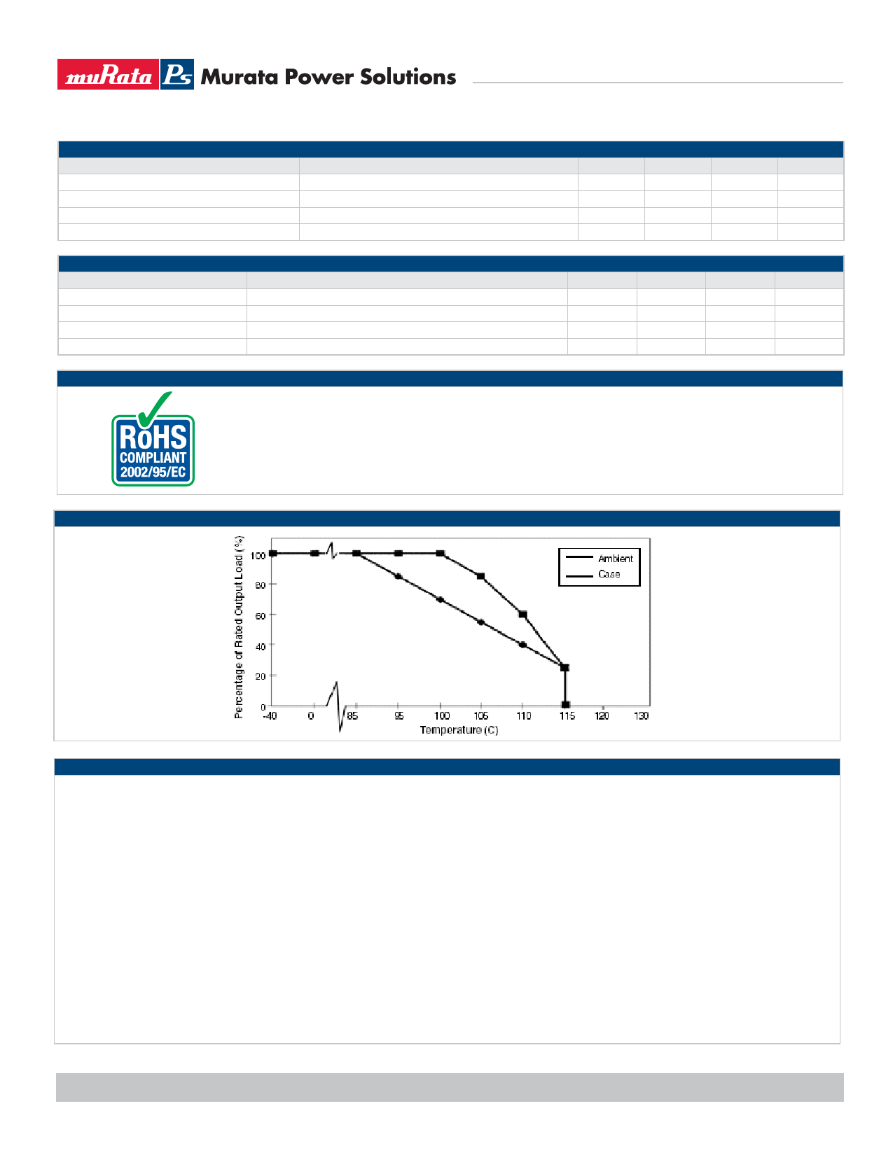
THERMAL DERATING CURVE
TECHNICAL NOTES
ISOLATION VOLTAGE
‘Hi Pot Test’, ‘Flash Tested’, ‘Withstand Voltage’, ‘Proof Voltage’, ‘Dielectric Withstand Voltage’ & ‘Isolation Test Voltage’ are all terms that relate to the same thing, a test voltage,
applied for a specified time, across a component designed to provide electrical isolation, to verify the integrity of that isolation.
Murata Power Solutions WPN20 series of dc/dc converters are all 100% production tested at their stated isolation voltage. This is 1500 Vpk for 10 seconds.
A question commonly asked is, “What is the continuous voltage that can be applied across the part in normal operation?”
The WPN20 series has been recognized by Underwriters Laboratory, both input and output should normally be maintained within SELV limits i.e. less than 42.4V peak, or 60VDC.
The isolation test voltage represents a measure of immunity to transient voltages and the part should never be used as an element of a safety isolation system. The part could be
expected to function correctly with several hundred volts offset applied continuously across the isolation barrier; but then the circuitry on both sides of the barrier must be regarded
as operating at an unsafe voltage and further isolation/insulation systems must form a barrier between these circuits and any user-accessible circuitry according to safety standard
requirements.
REPEATED HIGH-VOLTAGE ISOLATION TESTING
It is well known that repeated high-voltage isolation testing of a barrier component can actually degrade isolation capability, to a lesser or greater degree depending on materi-
als, construction and environment. While manufactured parts can withstand several times the stated test voltage, the isolation capability does depend on the wire insulation. Any
material, including this enamel (typically polyurethane) is susceptible to eventual chemical degradation when subject to very high applied voltages thus implying that the number of
tests should be strictly limited. We therefore strongly advise against repeated high voltage isolation testing, but if it is absolutely required, that the voltage be reduced by 20% from
specified test voltage.
www.murata-ps.com
Technical enquiries - email: mk@murata-ps.com, tel: +44 (0)1908 615232
KDC_WPN20RC.C01 Page 2 of 4
Share Link: 