HCPL-7100 データシートの表示(PDF) - HP => Agilent Technologies
部品番号
コンポーネント説明
メーカー
HCPL-7100 Datasheet PDF : 14 Pages
| |||
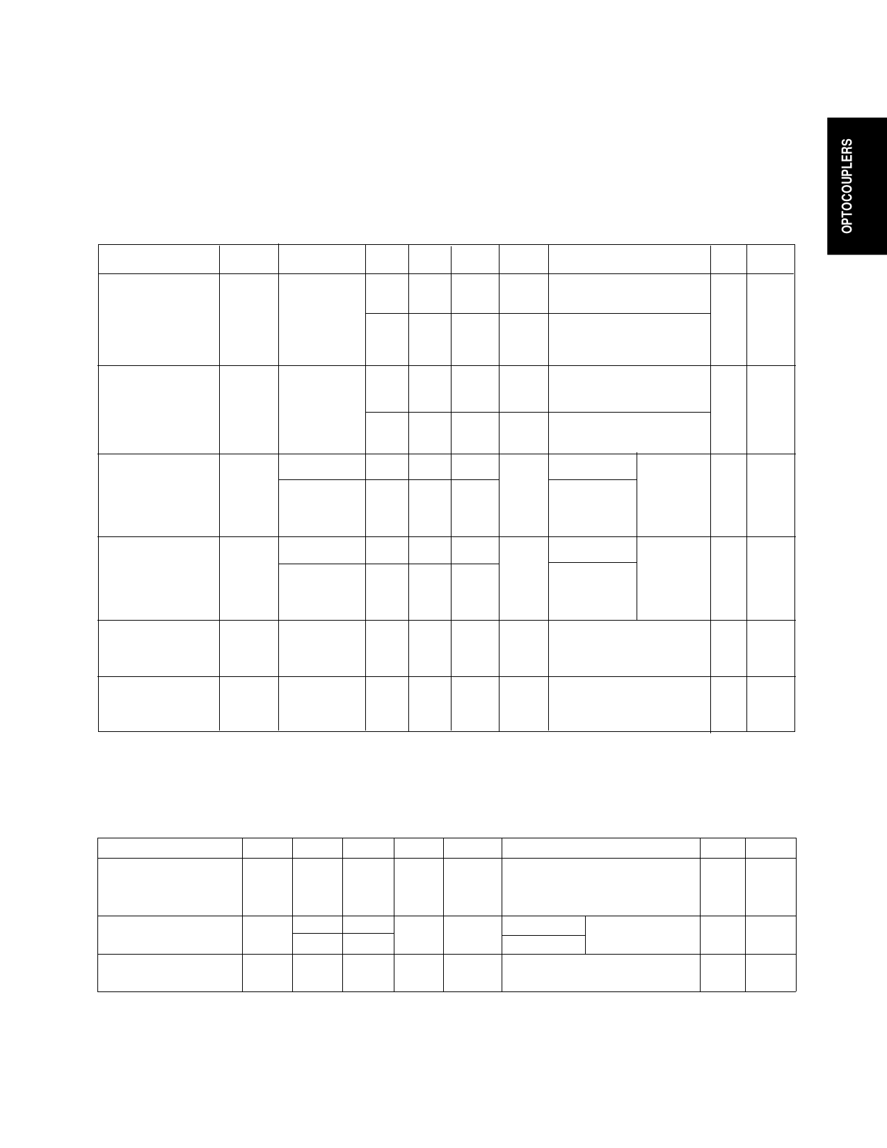
Switching Specifications (cont.)
Guaranteed across recommended operating conditions. Test conditions represent worst case values for the
parameter under test. Test conditions that are not specified can be anywhere within their operating range. All
typicals are at 25°C and 5 V supplies unless otherwise noted.
Parameter
Propagation
Delay Time from
Logic High to
Output Disabled
Symbol
tPHZ
Device
Min. Typ.
12
12
Max.
Unit
ns
ns
Test Conditions
CL = 50 pF
CMOS Signal Levels
CL = 15 pF
TTL Signal Levels
Fig. Note
12 6
Propagation
tPLZ
9
Delay Time from
Logic Low to
Output Disabled
11
Common Mode
Transient
Immunity at
Logic High
Output
Common Mode
Transient
Immunity at
Logic Low
Output
|CMH| HCPL-7100 1000
HCPL-7101 2000
|CML|
HCPL-7100 1000
HCPL-7101 2000
Input Dynamic
CPD1
68
Power Dissipation
Capacitance
Output Dynamic
CPD2
10
Power Dissipation
Capacitance
ns CL = 50 pF
CMOS Signal Levels
12 6
ns CL = 15 pF
TTL Signal Levels
V/µs VCM = 50 V VI = VIH
13, 10
VD > 3.2 V 14
VCM = 200 V
V/µs VCM = 50 V VI = VIL
13, 10
VD < 0.8 V 14
VCM = 200 V
pF
11
pF
11
Package Characteristics
Guaranteed across recommended operating conditions. Test conditions represent worst case value for the
parameter under test. Test conditions that are not specified can be anywhere within their operating range.
All typicals are at TA = 25°C and 5 V supplies unless otherwise noted.
Parameter
Sym. Min. Typ. Max. Units
Test Conditions
Fig. Note
Input-Output
Momentary
VISO 3750
Withstand Voltage*
V rms t = 1 min., RH < 50%,
2, 3
TA = 25°C
Input-Output
Resistance
Input-Output
Capacitance
RI-O 1012 1013
1011
CI-O
0.7
Ω
TA = 25°C VI-O = 500 Vdc
2
TA =100°C
pF f = 1 MHz
2
*The Input-Output Momentary Withstand Voltage is a dielectric voltage rating that should not be interpreted as an input-output
continuous voltage rating. For the continuous voltage rating refer to the VDE 0884 Insulation Characteristics Table (if applicable),
your equipment level safety specification or HP Application Note 1074 entitled “Optocoupler Input-Output Endurance Voltage.”
1-409
Share Link: 