MAX496 データシートの表示(PDF) - Maxim Integrated
部品番号
コンポーネント説明
メーカー
MAX496 Datasheet PDF : 12 Pages
| |||
375MHz Quad Closed-Loop
Video Buffers, AV = +1 and +2
MAX496/MAX497
MAX496/MAX497
50Ω
VIN = 4Vp-p,
f = 10MHz,
50Ω
RS = 75Ω
100Ω
100Ω
50Ω
50Ω
100Ω
100Ω
50Ω
100Ω
50Ω
100Ω
50Ω
100Ω
VIN = 4Vp-p,
f = 10MHz,
50Ω
100Ω
RS = 75Ω
a) ADJACENT CHANNEL
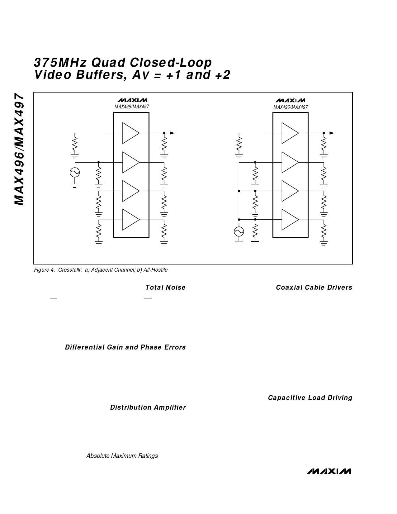
Figure 4. Crosstalk: a) Adjacent Channel; b) All-Hostile
b) ALL-HOSTILE
Total Noise
The MAX496/MAX497’s low input current noise of
2pA/√Hz and voltage noise of 5.6nV/√Hz provide for
lower total noise compared to typical current-mode-
feedback amplifiers, which usually have significantly
higher input current noise. The input current noise mul-
tiplied by the feedback resistor is the dominant noise
source of current-mode-feedback amplifiers.
Differential Gain and Phase Errors
Differential gain and phase errors are critical specifica-
tions for a buffer in composite (NTSC, PAL, SECAM) video
applications, because these errors correspond directly to
color changes in the displayed picture of composite video
systems. The MAX496/MAX497’s ultra-low differential gain
and phase errors (0.01%/ 0.01°) make them ideal in
broadcast-quality composite video applications.
Distribution Amplifier
The circuit in Figure 3 is a one-to-four distribution amplifier
using a single MAX496 or MAX497 IC. A one-to-eight dis-
tribution amplifier can be implemented with a MAX496 or
MAX497 by driving an additional cable from each of the
four outputs. When driving more than four outputs from a
single device, see the Continuous Power Dissipation
specifications in the Absolute Maximum Ratings.
Coaxial Cable Drivers
High-speed performance, excellent output current
capability, and an internally fixed gain of +2 make the
MAX497 ideal for driving back-terminated 50Ω or 75Ω
coaxial cables to ±2.8V.
In a typical application, the MAX497 drives a back-ter-
minated 75Ω video cable (Figure 1). The back-termina-
tion resistor (at the MAX497’s output) matches the
impedance of the cable’s driven end to the cable’s
impedance, to eliminate signal reflections. This, along
with the load-termination resistor, forms a voltage
divider with the load impedance, which attenuates the
signal at the cable output by one-half. The MAX497
operates with an internal +2V/V closed-loop gain to pro-
vide unity gain at the cable’s output.
Capacitive Load Driving
In most amplifier circuits, driving large capacitive loads
increases the likelihood of oscillation. This is especially
true for circuits with high loop gains, such as voltage
followers. The amplifier’s output resistance and the
capacitive load form an RC filter that adds a pole to the
loop response. If the pole frequency is low enough (as
when driving a large capacitive load), the circuit phase
margin is degraded and oscillation may occur.
10 ______________________________________________________________________________________
Share Link: 