MAX2451CSE データシートの表示(PDF) - Maxim Integrated
部品番号
コンポーネント説明
メーカー
MAX2451CSE Datasheet PDF : 6 Pages
| |||
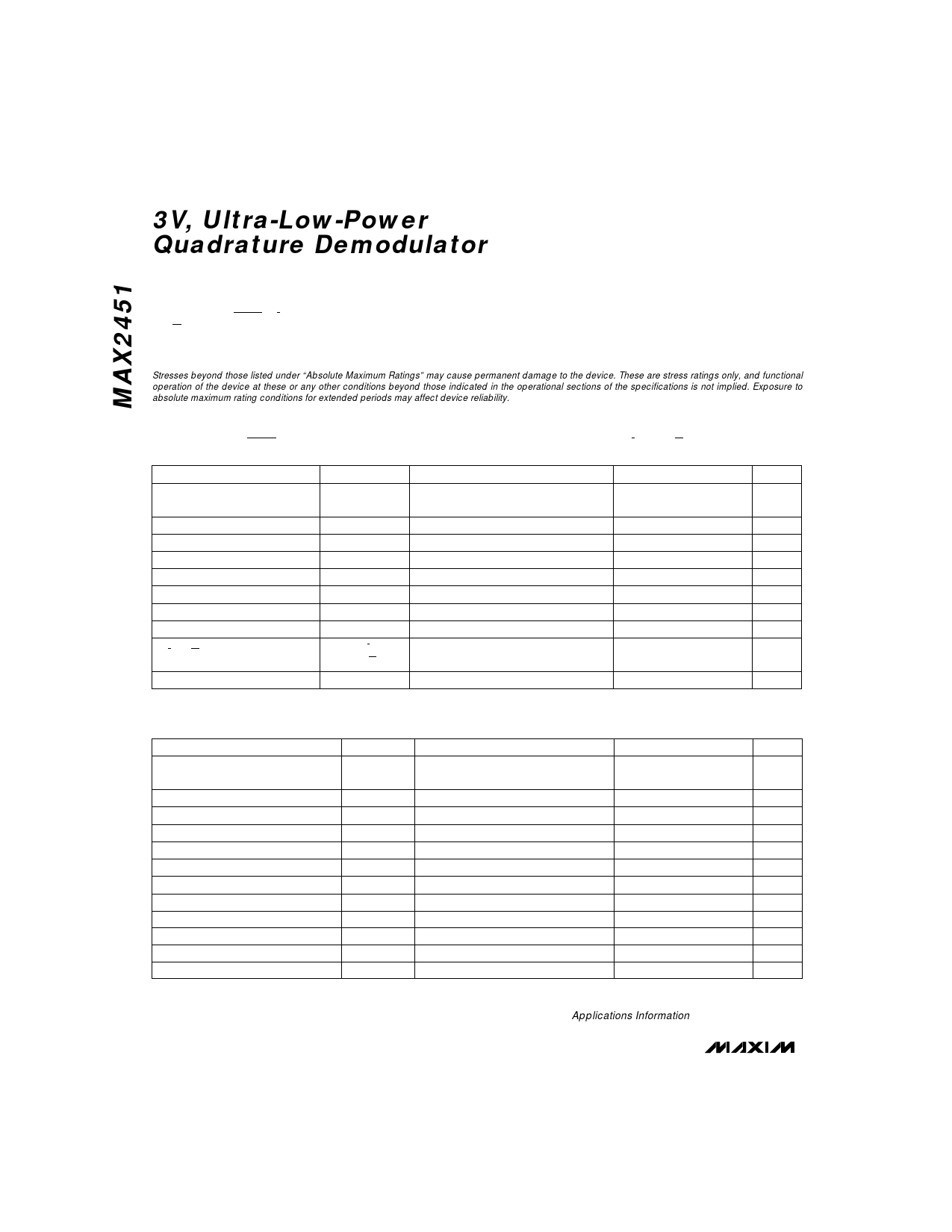
3V, Ultra-Low-Power
Quadrature Demodulator
ABSOLUTE MAXIMUM RATINGS
VCC, LO_VCC to GND............................................-0.3V to +4.5V
ENABLE, TANK, TANK, I, I,
Q, Q to GND.............................................-0.3V to (VCC + 0.3V)
IF to GND...............................................................-0.3V to +1.5V
Continuous Power Dissipation (TA = +70°C)
Narrow SO (derate 8.70mW/°C above +70°C) .............696mW
Operating Temperature Range...............................0°C to +70°C
Storage Temperature Range .............................-65°C to +165°C
Lead Temperature (soldering, 10sec) .............................+300°C
Stresses beyond those listed under “Absolute Maximum Ratings” may cause permanent damage to the device. These are stress ratings only, and functional
operation of the device at these or any other conditions beyond those indicated in the operational sections of the specifications is not implied. Exposure to
absolute maximum rating conditions for extended periods may affect device reliability.
DC ELECTRICAL CHARACTERISTICS
(VCC = LO_VCC = TANK = +2.7V to +3.3V, ENABLE = VCC - 0.4V, GND = LO_GND = 0V, I = I = Q = Q = IF = TANK = OPEN,
TA = 0°C to +70°C, unless otherwise noted.)
PARAMETER
SYMBOL
CONDITIONS
MIN TYP MAX UNITS
Supply Voltage Range
VCC,
LO_VCC
2.7
3.3
V
Supply Current
Shutdown Supply Current
Enable/Disable Time
ENABLE Bias Current
ENABLE High Voltage
ENABLE Low Voltage
IF Input Impedance
ICC(ON)
ICC(OFF)
tON/OFF
IEN
VENH
VENL
ZIN
Enable = 0.4V
5.5
7.4
mA
2
20
µA
10
µs
1
3
µA
VCC - 0.4
V
0.4
V
320
400
480
Ω
I, I, Q, Q Voltage Level
VI/I,
VQ/Q
1.2
V
Baseband I and Q DC Offset
±11
±50
mV
AC ELECTRICAL CHARACTERISTICS
VCC = LO_VCC = ENABLE = 3.0V, fLO = 140MHz, fIF = 70.1MHz, VIF = 2.82mVp-p, TA = +25°C, unless otherwise noted.)
PARAMETER
SYMBOL
CONDITIONS
MIN TYP MAX UNITS
Baseband I and Q Amplitude
Balance
Baseband I and Q Phase Accuracy
Voltage Conversion Gain
Noise Figure
Allowable I and Q Voltage Swing
I and Q IM3 Level
I and Q IM5 Level
I and Q Signal 3dB Bandwidth
Oscillator Frequency Range
PRE_OUT Output Voltage
PRE_OUT Slew Rate
Oscillator Phase Noise
NF
IM3I/Q
IM5I/Q
BW3dB
fLO
VPRE_OUT
SRPRE_OUT
(Note 1)
(Note 2)
(Note 2)
(Notes 1, 3)
RL = 10kΩ, CL < 6pF
RL = 10kΩ, CL < 6pF, rising edge
Offset = 10kHz
< ±0.45
dB
< ±1.3
degrees
51
dB
18
dB
1.35 Vp-p
-44
dBc
-60
dBc
9
MHz
70
160 MHz
0.35
Vp-p
60
V/µs
-80
dBc/Hz
Note 1: Guaranteed by design, not tested.
Note 2: fIF = 2 tones at 70.10MHz and 70.11MHz, VIF = 1.41mVp-p per tone.
Note 3: Oscillator frequencies up to 1GHz (500MHz IF) by externally overdriving (see Applications Information).
2 _______________________________________________________________________________________
Share Link: 