MAX2451CSE データシートの表示(PDF) - Maxim Integrated
部品番号
コンポーネント説明
メーカー
MAX2451CSE Datasheet PDF : 6 Pages
| |||
3V, Ultra-Low-Power
Quadrature Demodulator
_____________________Pin Description
PIN
1
2, 3, 16
4
5
6
7
8
9
10
11
12
13
14
15
NAME
IF
GND
N.C.
ENABLE
PRE_OUT
LO_VCC
TANK
TANK
LO_GND
Q
Q
I
I
VCC
FUNCTION
IF Input
Ground
No Connect. No internal connec-
tion to this pin.
Enable Control, active high
Local-Oscillator Divide-by-8
Prescaled Output
Local-Oscillator Supply. Bypass
separately from VCC.
Local-Oscillator Resonant Tank
Input
Local-Oscillator Resonant Tank
Inverting Input
Local-Oscillator Ground
Baseband Quadrature Inverting
Output
Baseband Quadrature Output
Baseband Inphase Inverting
Output
Baseband Inphase Output
Demodulator Supply
DOWNCONVERTER
0˚
90˚
MAX2451
÷8
2
A/D
POST
PROCESSING
2
A/D
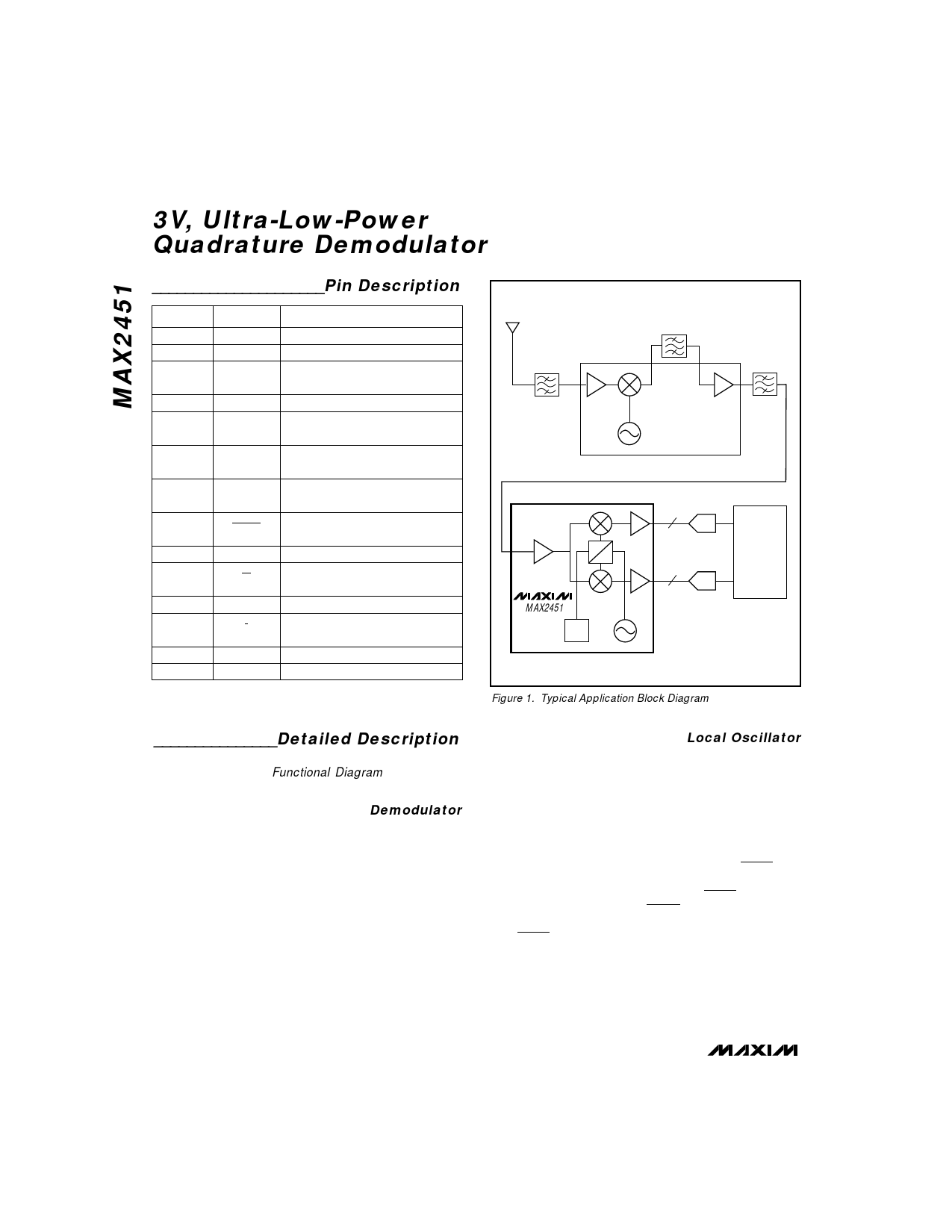
Figure 1. Typical Application Block Diagram
_______________Detailed Description
The following sections describe each of the functional
blocks shown in the Functional Diagram. Also refer to
the Typical Application Block Diagram (Figure 1).
Demodulator
The demodulator contains a single-ended-to-differential
converter, two Gilbert-cell multipliers, and two fixed
gain stages. Internally, IF is terminated with a 400Ω
resistor to GND. The IF input signal is AC coupled into
the input amplifier, which has 14dB of gain. This ampli-
fied IF signal is fed into the I and Q channel mixers for
demodulation. The multipliers mix the IF signal with the
quadrature LO signals, resulting in baseband I and Q
signals. The conversion gain of the multipliers is 15dB.
These signals are further amplified by 21dB by the
baseband amplifiers. The baseband amplifier chains
are DC coupled.
Local Oscillator
The local-oscillator section is formed by an emitter-cou-
pled differential pair. Figure 2 shows the local-oscillator
equivalent circuit schematic. An external LC resonant
tank determines the oscillation frequency, and the Q of
this resonant tank affects the oscillator phase noise.
The oscillation frequency is twice the IF frequency, for
easy generation of quadrature signals.
The oscillator may be overdriven by an external source.
The source should be AC coupled into TANK/TANK, and
should provide 200mVp-p levels. A choke (typically
2.2µH) is required between TANK and TANK. Differential
input impedance at TANK/TANK is 10kΩ. For single-
ended drive, connect an AC bypass capacitor (1000pF)
from TANK to GND, and AC couple TANK to the source.
The oscillator can be overdriven at frequencies up to
1GHz (500MHz IF), but conversion gain and prescaler
output levels will be somewhat reduced.
4 _______________________________________________________________________________________
Share Link: 