MAX2451CSE データシートの表示(PDF) - Maxim Integrated
部品番号
コンポーネント説明
メーカー
MAX2451CSE Datasheet PDF : 6 Pages
| |||
3V, Ultra-Low-Power
Quadrature Demodulator
LO_VCC
RL
RL
5k
5k
Q3
TANK TANK
Q4
Q1
Q2
TO QUADRATURE
GENERATOR AND
PRESCALER
TANK
C1 = 33pF
47k
L = 100nH
TANK
C2 = 33pF
1/2 KV1410
10k
1/2 KV1410
47k
0.1µF
VCTRL
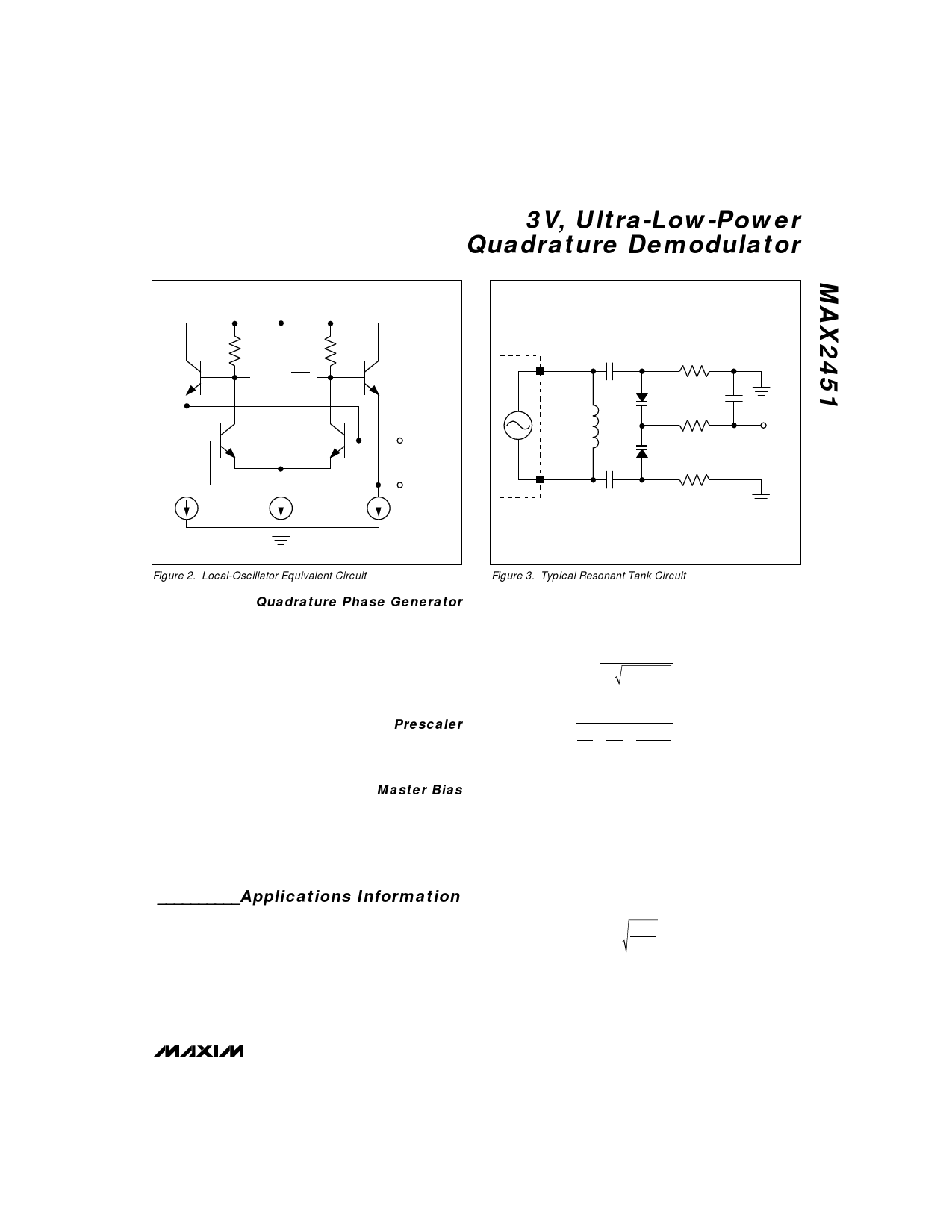
Figure 2. Local-Oscillator Equivalent Circuit
Quadrature Phase Generator
The quadrature phase generator uses two latches to
divide the local-oscillator frequency by two, and gener-
ates two precise quadrature signals. Internal limiting
amplifiers shape the signals to approximate square
waves to drive the Gilbert-cell mixers. The inphase sig-
nal (at half the local oscillator frequency) is further
divided by four for the prescaler output.
Prescaler
The prescaler output, PRE_OUT, is buffered and swings
typically 0.35Vp-p with a 10kΩ and 6pF load. It can be
AC coupled to the input of a frequency synthesizer.
Master Bias
During normal operation, ENABLE should be above
VCC - 0.4V. Pulling the ENABLE input low shuts off the
master bias and reduces the circuit current to typically
2µA. The master bias section includes a bandgap ref-
erence generator and a PTAT (Proportional To Absolute
Temperature) current generator.
__________Applications Information
Figure 3 shows the implementation of a resonant tank
circuit. The inductor, two capacitors, and a dual varac-
tor form the oscillator’s resonant circuit. In Figure 3, the
oscillator frequency ranges from 130MHz to 160MHz.
To ensure reliable start-up, the inductor is directly con-
nected across the local oscillator’s tank ports. The two
33pF capacitors affect the Q of the resonant circuit.
Other values may be chosen to meet individual appli-
Figure 3. Typical Resonant Tank Circuit
cation requirements. The oscillation frequency can be
determined using the following formula:
fo =
1
2π LEQCEQ
where
CEQ =
1+
1
1+
2
+ CSTRAY
C1 C2 CVAR
and
LEQ = L + LSTRAY
where CSTRAY = parasitic capacitance and LSTRAY =
parasitic inductance.
To alter the oscillation frequency range, change the
inductance, the capacitance, or both. For best phase-
noise performance, keep the Q of the resonant tank as
high as possible:
Q = REQ CEQ
LEQ
where REQ ≈ 10kΩ (Figure 2).
The oscillation frequency can be changed by altering
the control voltage, VCTRL.
_______________________________________________________________________________________ 5
Share Link: 