ISL88705(2006) гГЗгГЉгВњгВЈгГЉгГИгБЃи°®з§ЇпЉИPDFпЉЙ - Intersil
йГ®еУБзХ™еПЈ
гВ≥гГ≥гГЭгГЉгГНгГ≥гГИи™ђжШО
гГ°гГЉгВЂгГЉ
ISL88705
(Rev.:2006)
(Rev.:2006)
Intersil

ISL88705 Datasheet PDF : 14 Pages
| |||
ISL88705, ISL88706, ISL88707, ISL88708, 8SL88716, ISL88813
Manual Reset
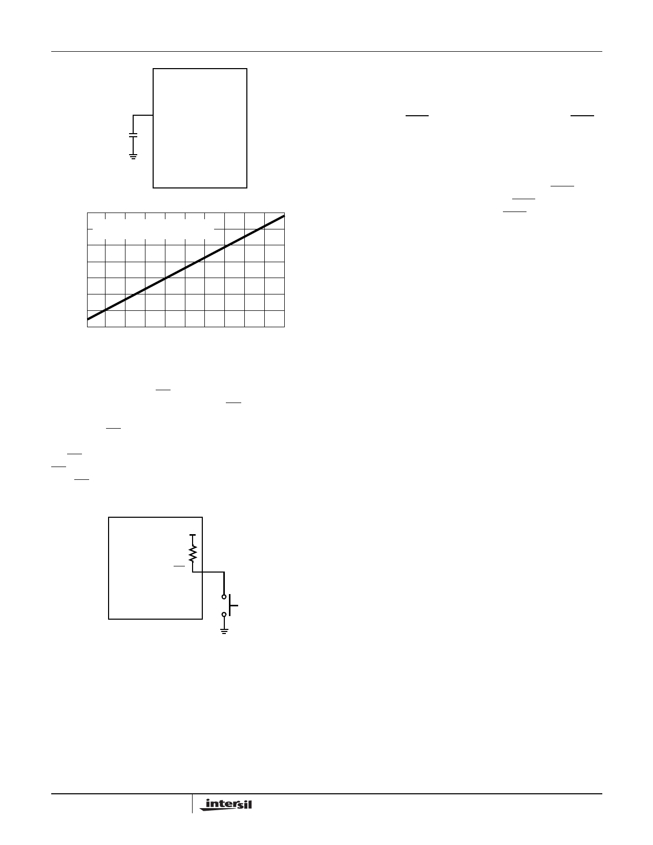
The manual-reset input (MR) allows the user to trigger a
reset by using a push-button switch. The MR input is an
active low debounced input. By connecting a push-button
directly from MR to ground, the designer adds manual
system reset capability (see Figure 4). Reset is asserted if
the MR pin is pulled low to less than 100mV for the minimum
MR pulse width or longer while the push-button is closed.
After MR is released, the reset outputs remain asserted for
tPOR (200ms) and then released.
20k
MR
Watchdog Timer
The Watchdog Timer circuit checks microprocessor activity
by monitoring the WDI input pin. The microprocessor must
periodically toggle the WDI pin within tWDT (typically 1.6s),
otherwise the WDO pin goes low (see Figure 5). Internally,
the 1.6s timer is cleared by either a reset or by toggling the
WDI input, which can detect pulses longer than 50ns.
Whenever there is a low-voltage VDD condition, WDO goes
low. Unlike the reset outputs, however, WDO does not have
a minimum reset pulse width (tPOR). WDO goes high as
soon as VDD rises above its voltage trip point (see Figure 5).
With WDI open or connected to a tristated high impedance
input, the Watchdog Timer is disabled and only pulls low
when VDD < VTH1.
PB
ISL8870X
FIGURE 4. CONNECTING A MANUAL RESET PUSH-BUTTON
VDD
VTH1
1V
WDI
WDO
RST
< tWDT
< tWDT
tWDT
< tWDT
tPOR
>tWDPS
tPOR
tRPD
FIGURE 5. WATCHDOG TIMING DIAGRAM
tPOR
8
FN8092.3
December 6, 2006
Share Link: